
Guía de instalación y operación
Controlador Omega
Guía de instalación y operación · Rev. H · PIEAE20-OMEGA
1. Safety
Safety Conventions
Esta sección aún no está traducida y se muestra en inglés.
Indicates a potentially hazardous situation, which, if not avoided, could result in injury or death.
Indicates that the equipment or environment can be damaged, or data can be corrupted.
Indicates additional information to help the user obtain optimum performance. Notes are not safety-related to the equipment or personnel.
Indicates useful information to simplify steps or procedures.
Safety Instructions
Esta sección aún no está traducida y se muestra en inglés.
Prior to performing any work on the Omega controller, become familiar with the following safety concerns: General Safety Instructions, Battery Safety Instructions, and External Power Source Safety Instructions.
General Safety Instructions
- Read this installation and operation guide prior to installing and servicing the system.
- Pay careful attention to all cautions and warnings in this guide.
- Installation must comply with all local electrical and plumbing codes.
- It is recommended that a licensed electrician performs all electrical connections. Improper installation could result in shock or fire hazard.
- Omega is not intended for use by children.
Battery Safety Instructions
- BERMAD is not responsible for battery failures due to mishandling.
- Do not crush, break, or disassemble the batteries.
- Do not damage the battery label, which acts as an electrical insulation for the battery can.
- Do not install the batteries backwards, put in fire, submerge in fluids, or mix with other battery types.
- Do not weld or solder the batteries onto the battery compartment.
- Dispose of batteries in accordance with local regulations.
- Internal batteries are intended for offline mode operation.
- Contact BERMAD for battery replacement when depleted or damaged.
External Power Source Safety Instructions
Contact with electrical connections can cause electric shock if the power supply is turned on.
- Before connecting to an external power source, ensure the external power polarity matches the one marked on the Omega connector board.
- The power supply cables must first be connected to the Omega power connectors before plugging into an external power source.
- The Omega controller must first be unplugged from the external power source before disconnecting the power supply cables from the power connectors.
FCC Notice
Esta sección aún no está traducida y se muestra en inglés.
This equipment has been tested and found to comply with the limits for a Class A digital device, pursuant to part 15 of the FCC Rules. These limits are designed to provide reasonable protection against harmful interference when the equipment is operated in a commercial environment. This equipment generates, uses, and can radiate radio frequency energy and, if not installed and used in accordance with the instruction manual, may cause harmful interference to radio communications. Operation of this equipment in a residential area is likely to cause harmful interference in which case the user will be required to correct the interference at his own expense.
Declaration of Conformity
Esta sección aún no está traducida y se muestra en inglés.
This equipment has been tested and found to comply with EN 61010-1:2010 and IEC 61010-1:2010, AMD1:2016 standards.
Omega Controller Nameplate
Esta sección aún no está traducida y se muestra en inglés.
The Omega controller nameplate is located on the back of the controller. It contains the following information:
- Model type (Omega S, Omega RS, Omega L)
- Manufacture date
- Serial number
- QR code (contains serial number, link to BERMAD cloud, and encrypted controller activation code)
- Activation code
- Power source data
2. Introduction
Overview
Esta sección aún no está traducida y se muestra en inglés.
Omega is an advanced cloud-based irrigation controller. It provides a user-friendly and cost-effective solution for irrigation heads as well as water distribution, data acquisition, and pre-paid systems.
Controller Features
- Volumetric and time-based irrigation.
- High/low flow monitoring (when used with a water meter).
- Leak detection.
- Four different models: 4-13 outputs, 4/8 digital inputs and 2 analog inputs.
- Comprehensive log registry allows for long periods of offline operation.
- Real-time alert notifications to a PC, tablet, and smartphone.
- Realtime operation powered by an external power source.
- Technician mode debugging via BLE.
- Energy save mode operation (designed for conserving energy) powered by internal batteries.
- Industrial grade electronic components (-35 °C-31 °F to 75 °C167 °F).
- IP65 rated with UV protection for outdoor installation.
- CE and FCC standard compliant.
Communication Features
- Built-in GSM modem with global data SIM card for worldwide Internet connectivity.
- Secured end-to-end communication using 4G modem with 2G fallback.
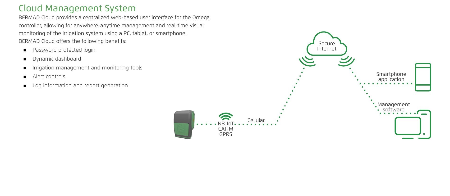
- Supports NB-IoT, CAT-M, and GPRS protocols.
Typical Connection Layout
Esta sección aún no está traducida y se muestra en inglés.
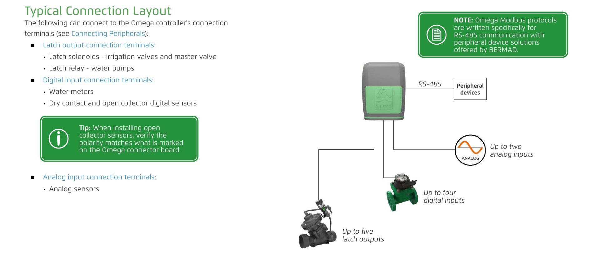
The following can connect to the Omega controller's connection terminals (see Connecting Peripherals):
Latch output connection terminals
- Latch solenoids - irrigation valves and master valve
- Latch relay - water pumps
Digital input connection terminals
- Water meters
- Dry contact and open collector digital sensors
Analog input connection terminals
- Analog sensors
Up to five latch outputs, up to four digital inputs, up to two analog inputs, RS-485 for peripheral devices.
Omega Modbus protocols are written specifically for RS-485 communication with peripheral device solutions offered by BERMAD.
When installing open collector sensors, verify the polarity matches what is marked on the Omega connector board.
Omega Controller
Esta sección aún no está traducida y se muestra en inglés.
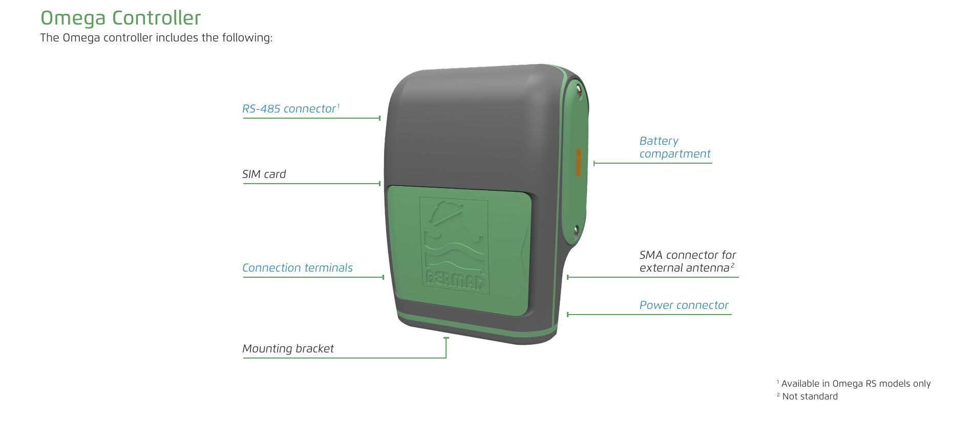
The Omega controller includes the following:
- RS-485 connector (Available in Omega RS models only)
- Battery compartment
- SIM card
- SMA connector for external antenna (Not standard)
- Connection terminals
- Power connector
- Mounting bracket
Cloud Management System
Esta sección aún no está traducida y se muestra en inglés.
BERMAD Cloud provides a centralized web-based user interface for the Omega controller, allowing for anywhere-anytime management and real-time visual monitoring of the irrigation system using a PC, tablet, or smartphone.
BERMAD Cloud offers the following benefits:
- Password protected login
- Dynamic dashboard
- Irrigation management and monitoring tools
- Alert controls
- Log information and report generation
3. Installation
Mounting Omega
Esta sección aún no está traducida y se muestra en inglés.
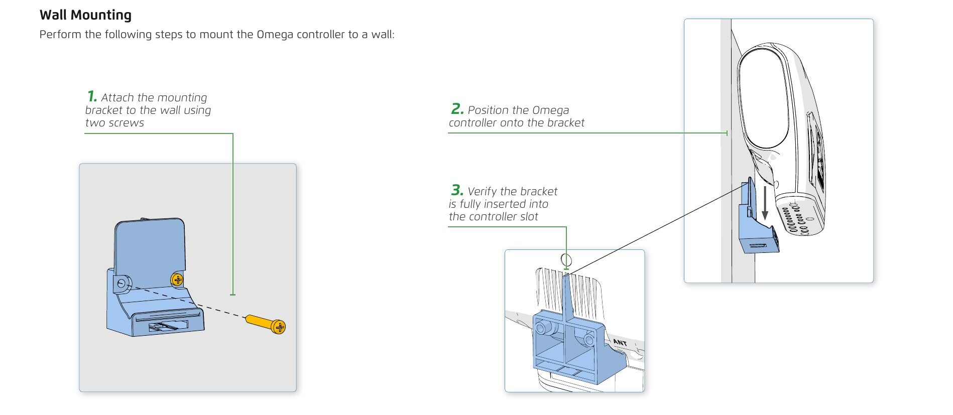
Wall Mounting
Perform the following steps to mount the Omega controller to a wall:
- Attach the mounting bracket to the wall using two screws
- Position the Omega controller onto the bracket
- Verify the bracket is fully inserted into the controller slot
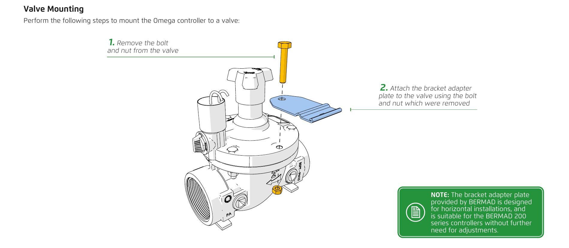
Valve Mounting
Perform the following steps to mount the Omega controller to a valve:
- Remove the bolt and nut from the valve
- Attach the bracket adapter plate to the valve using the bolt and nut which were removed
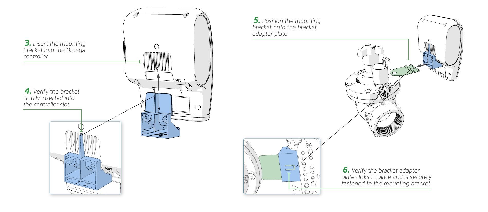
- Insert the mounting bracket into the Omega controller
- Verify the bracket is fully inserted into the controller slot
- Position the mounting bracket onto the bracket adapter plate
- Verify the bracket adapter plate clicks in place and is securely fastened to the mounting bracket
The bracket adapter plate provided by BERMAD is designed for horizontal installations, and is suitable for the BERMAD 200 series controllers without further need for adjustments.
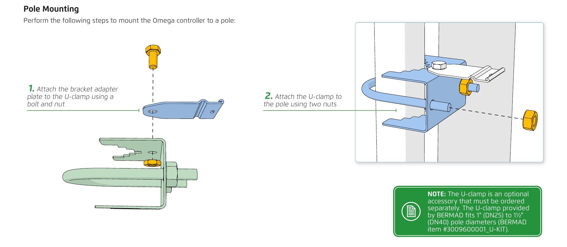
Pole Mounting
Perform the following steps to mount the Omega controller to a pole:
- Attach the bracket adapter plate to the U-clamp using a bolt and nut
- Attach the U-clamp to the pole using two nuts
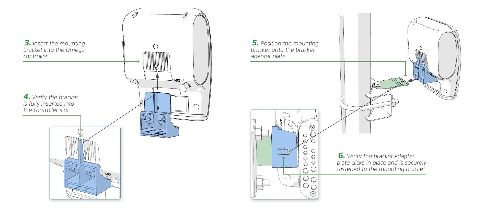
- Insert the mounting bracket into the Omega controller
- Verify the bracket is fully inserted into the controller slot
- Position the mounting bracket onto the bracket adapter plate
- Verify the bracket adapter plate clicks in place and is securely fastened to the mounting bracket
The U-clamp is an optional accessory that must be ordered separately. The U-clamp provided by BERMAD fits 1" (DN25) to 1½" (DN40) pole diameters (BERMAD item #3009600001_U-KIT).
Powering Omega
Esta sección aún no está traducida y se muestra en inglés.
Battery Power Supply
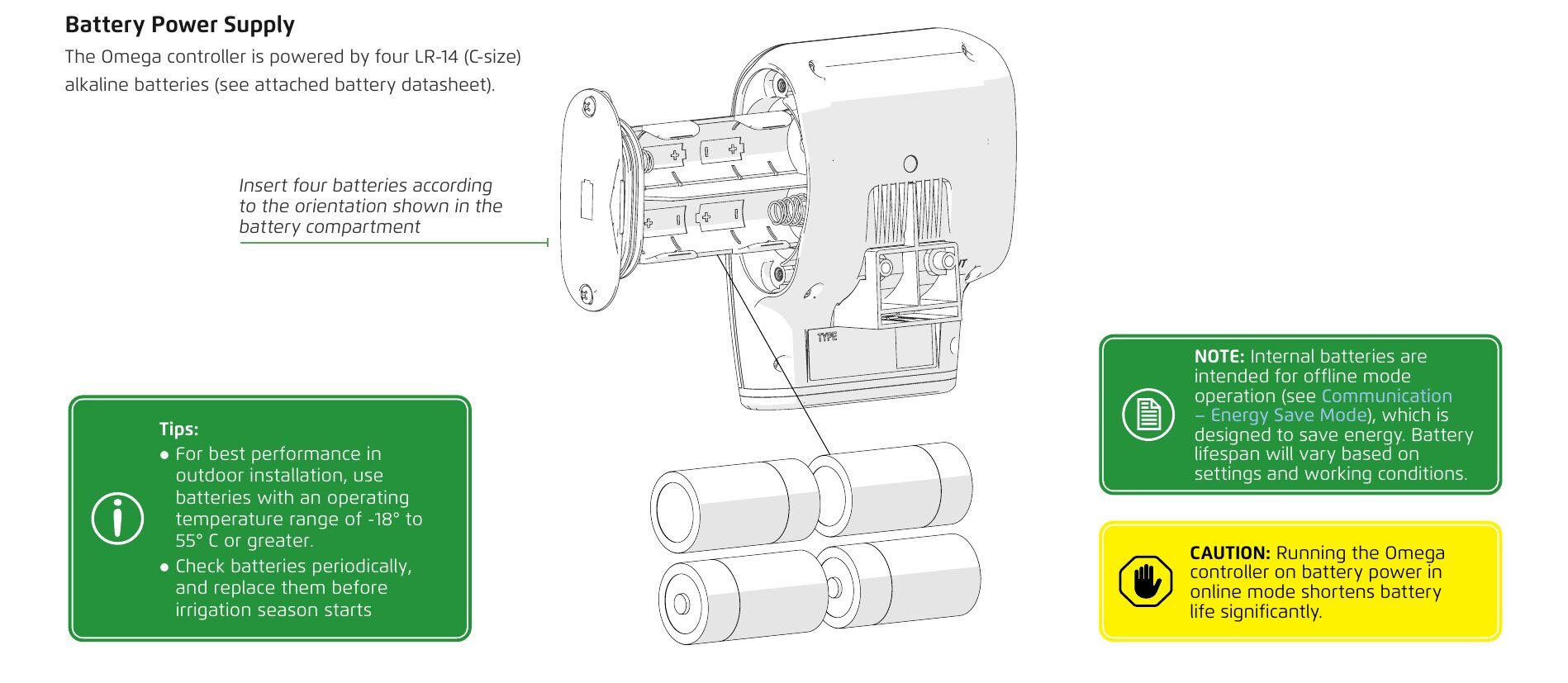
The Omega controller is powered by four LR-14 (C-size) alkaline batteries (see attached battery datasheet).
Insert four batteries according to the orientation shown in the battery compartment.
For best performance in outdoor installation, use batteries with an operating temperature range of -18° to 55° C or greater.
Check batteries periodically, and replace them before irrigation season starts.
Internal batteries are intended for offline mode operation (see Communication – Energy Save Mode), which is designed to save energy. Battery lifespan will vary based on settings and working conditions.
Running the Omega controller on battery power in online mode shortens battery life significantly.
External Power Source
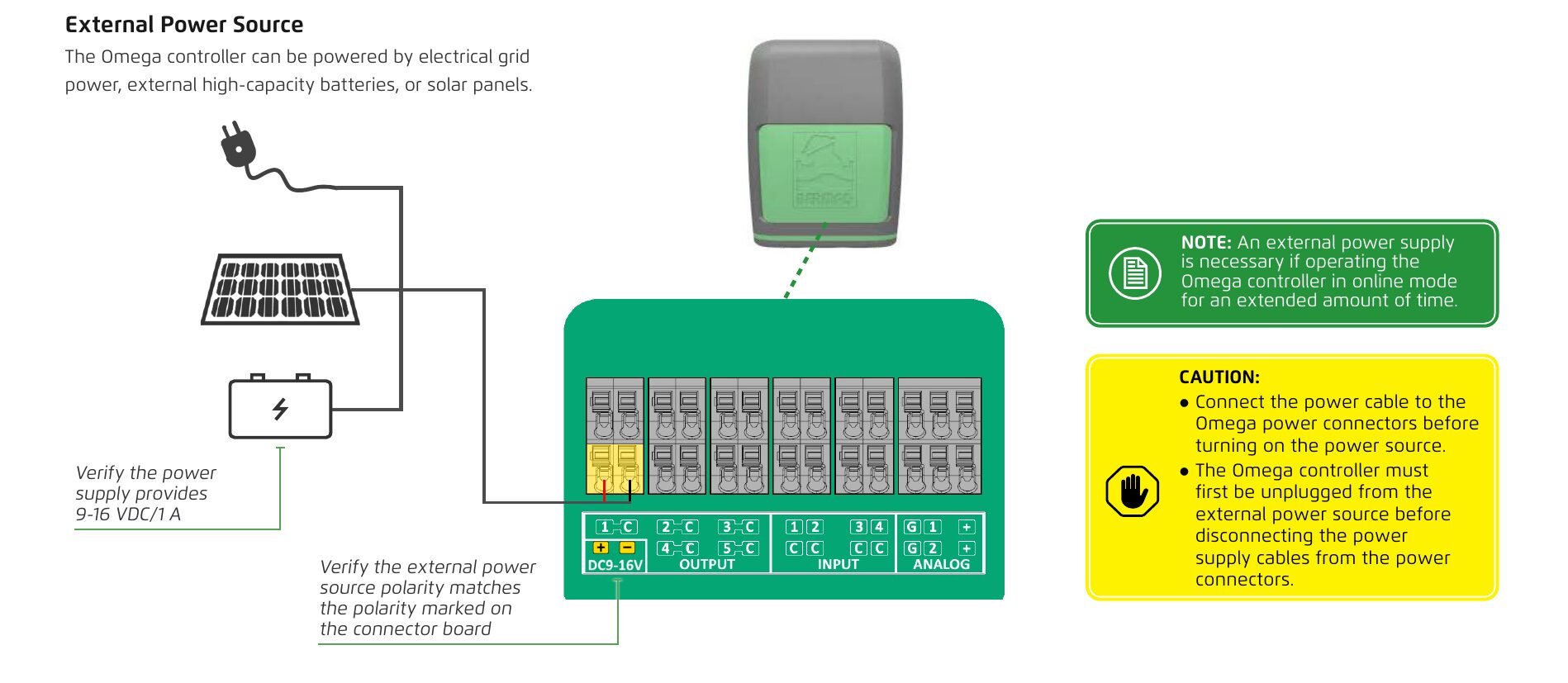
The Omega controller can be powered by electrical grid power, external high-capacity batteries, or solar panels.
Verify the power supply provides 9-16 VDC/1 A.
Verify the external power source polarity matches the polarity marked on the connector board.
Connect the power cable to the Omega power connectors before turning on the power source. The Omega controller must first be unplugged from the external power source before disconnecting the power supply cables from the power connectors.
An external power supply is necessary if operating the Omega controller in online mode for an extended amount of time.
Connecting Peripherals
Esta sección aún no está traducida y se muestra en inglés.
Latch Output Connections
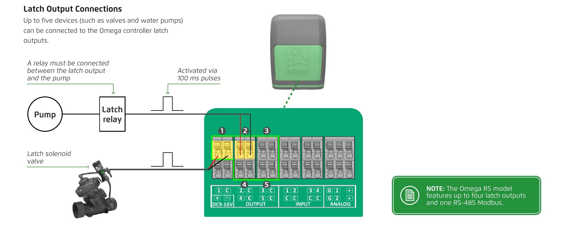
Up to five devices (such as valves and water pumps) can be connected to the Omega controller latch outputs.
A relay must be connected between the latch output and the pump. Pump activated via 100 ms pulses.
The Omega RS model features up to four latch outputs and one RS-485 Modbus.
Digital Input Connections
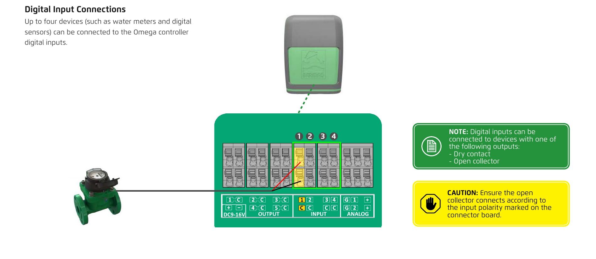
Up to four devices (such as water meters and digital sensors) can be connected to the Omega controller digital inputs.
Digital inputs can be connected to devices with one of the following outputs:
- Dry contact
- Open collector
Ensure the open collector connects according to the input polarity marked on the connector board.
Analog Input Connections
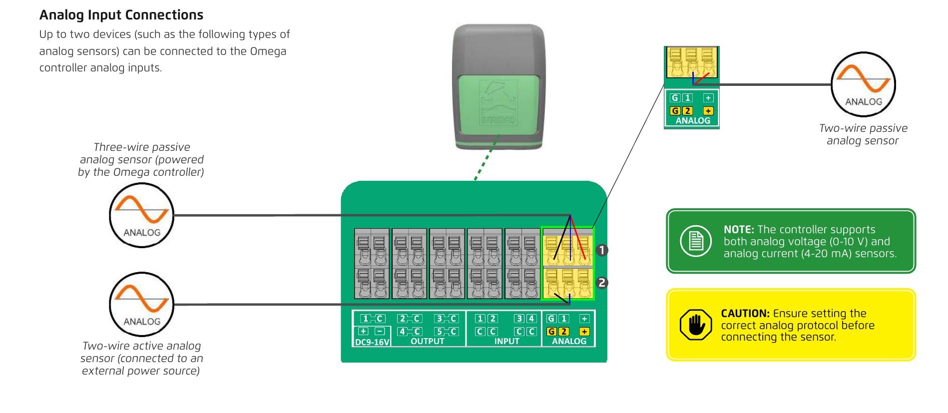
Up to two devices (such as the following types of analog sensors) can be connected to the Omega controller analog inputs.
- Two-wire passive analog sensor
- Three-wire passive analog sensor (powered by the Omega controller)
- Two-wire active analog sensor (connected to an external power source)
The controller supports both analog voltage (0-10 V) and analog current (4-20 mA) sensors.
Ensure setting the correct analog protocol before connecting the sensor.
Communicating with Omega
Esta sección aún no está traducida y se muestra en inglés.
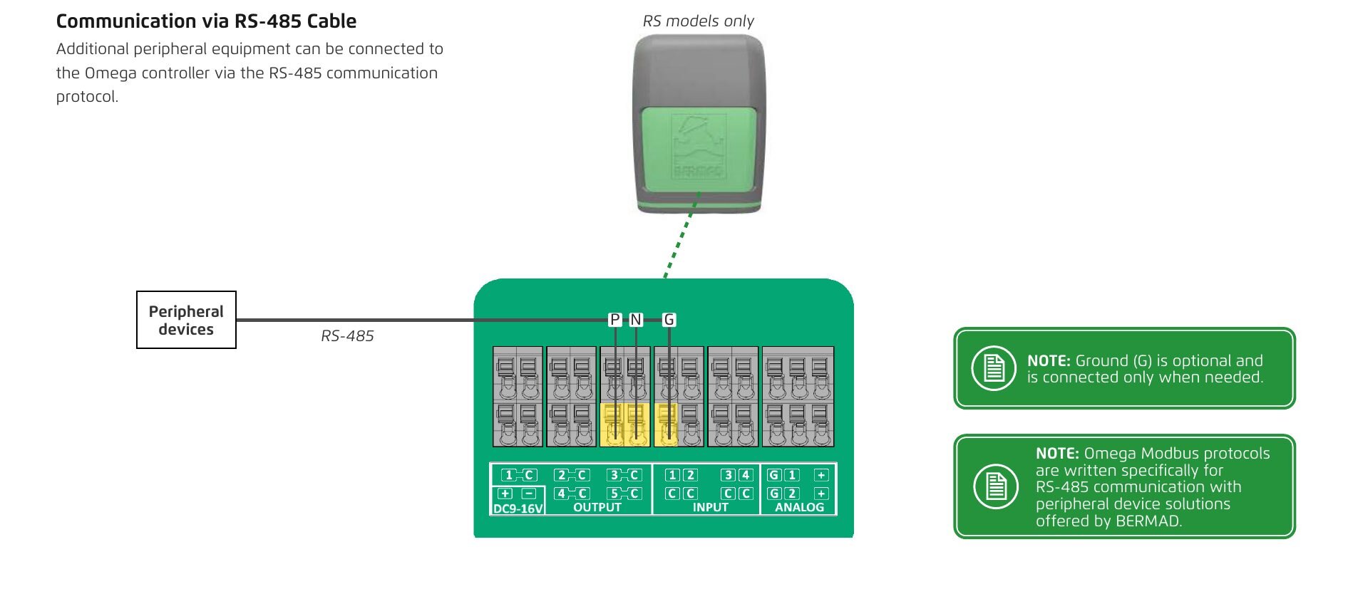
Communication via RS-485 Cable
RS models only
Additional peripheral equipment can be connected to the Omega controller via the RS-485 communication protocol.
Ground (G) is optional and is connected only when needed.
Omega Modbus protocols are written specifically for RS-485 communication with peripheral device solutions offered by BERMAD.
Communicating via BERMAD Cloud
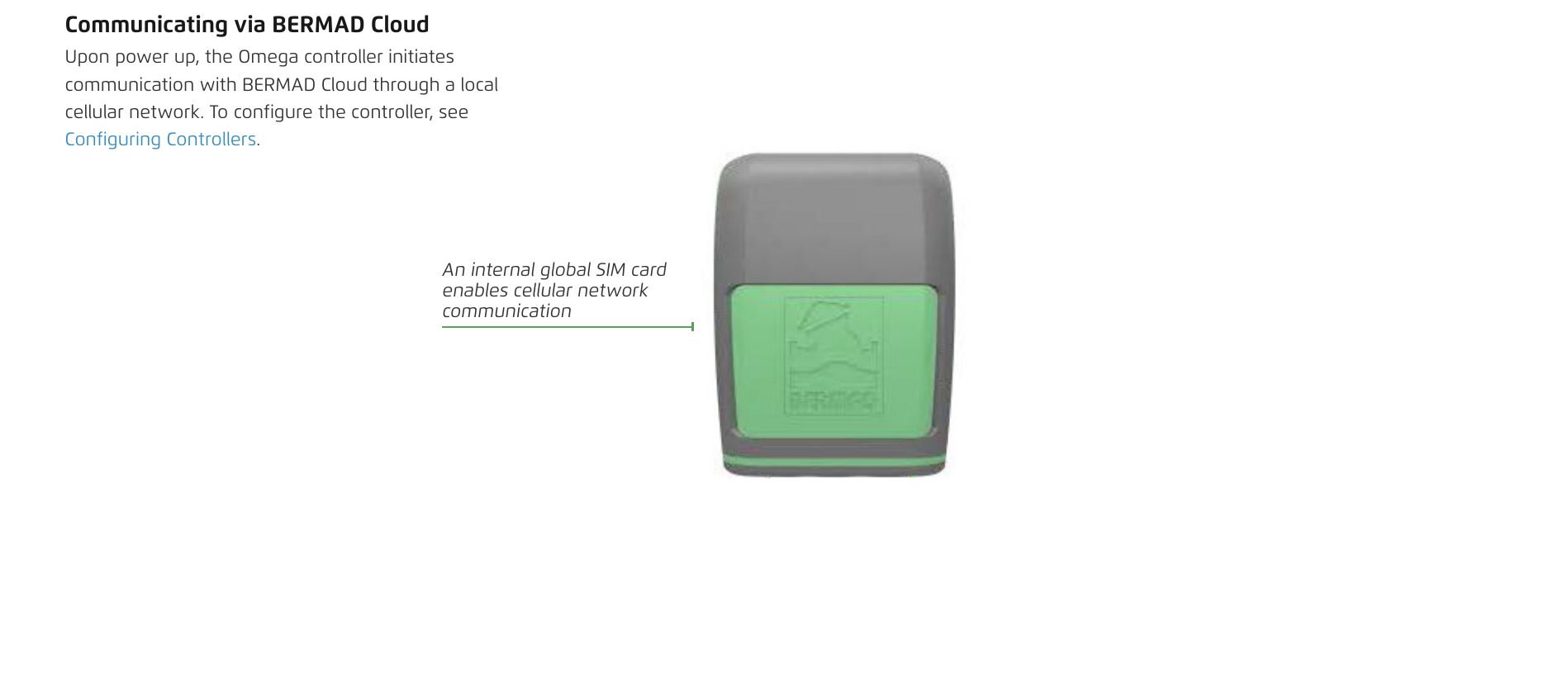
Upon power up, the Omega controller initiates communication with BERMAD Cloud through a local cellular network. To configure the controller, see Configuring Controllers.
An internal global SIM card enables cellular network communication.
Omega M and Omega L Controllers
Esta sección aún no está traducida y se muestra en inglés.
Output, Input, and Analog Connections
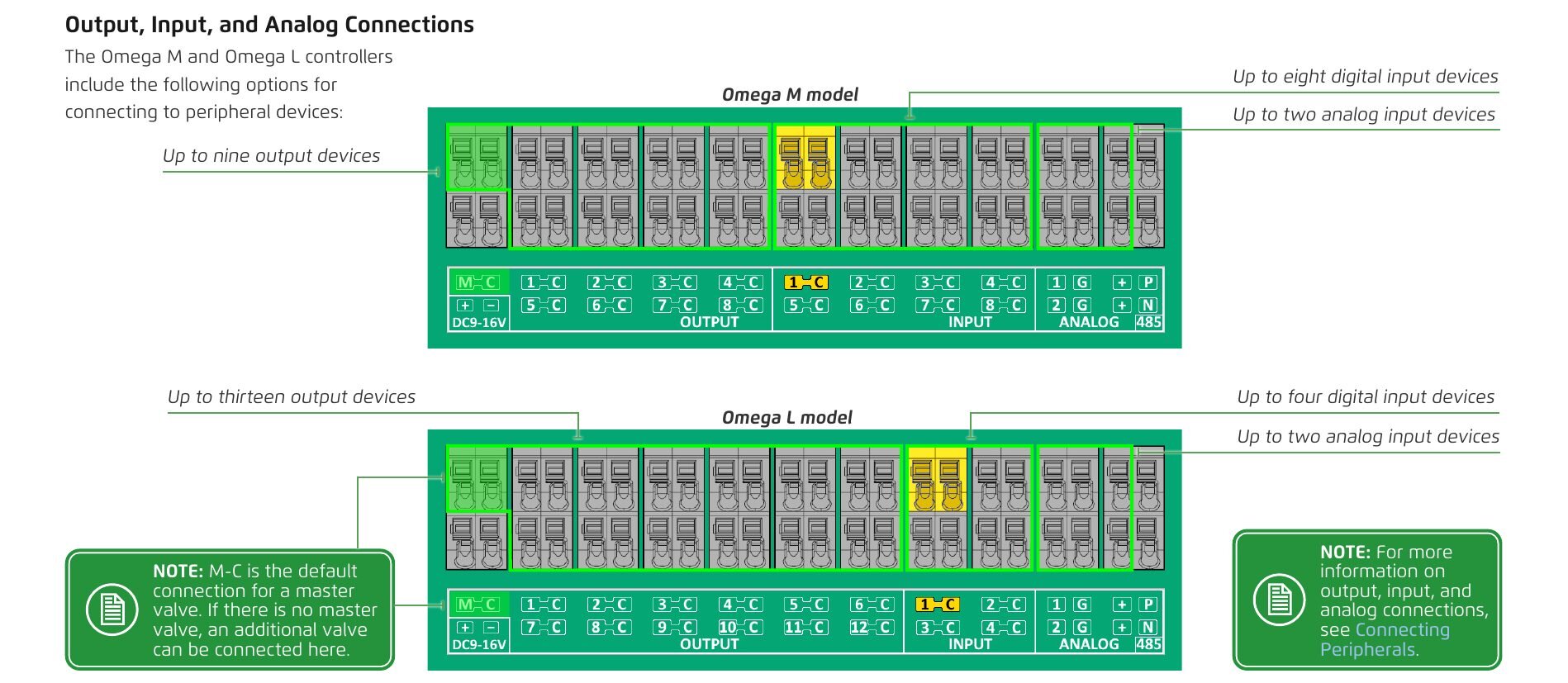
The Omega M and Omega L controllers include the following options for connecting to peripheral devices:
Omega M model
- Up to eight digital input devices
- Up to two analog input devices
- Up to nine output devices
Omega L model
- Up to thirteen output devices
- Up to four digital input devices
- Up to two analog input devices
M-C is the default connection for a master valve. If there is no master valve, an additional valve can be connected here.
For more information on output, input, and analog connections, see Connecting Peripherals.
4. Configuring Controllers
Downloading BERMAD Cloud App
Esta sección aún no está traducida y se muestra en inglés.
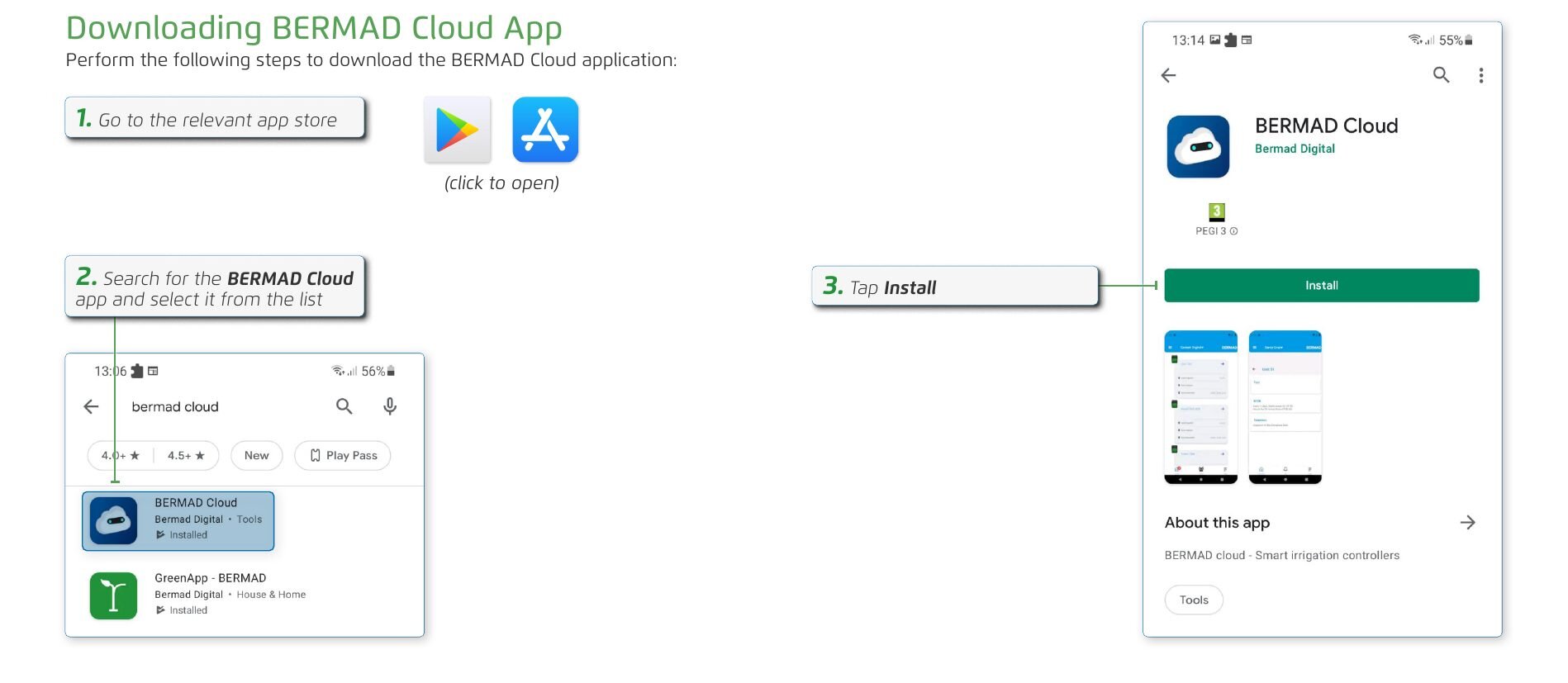
Perform the following steps to download the BERMAD Cloud application:
- Go to the relevant app store (click to open).
- Search for the BERMAD Cloud app and select it from the list.
- Tap Install.
Registering
Esta sección aún no está traducida y se muestra en inglés.
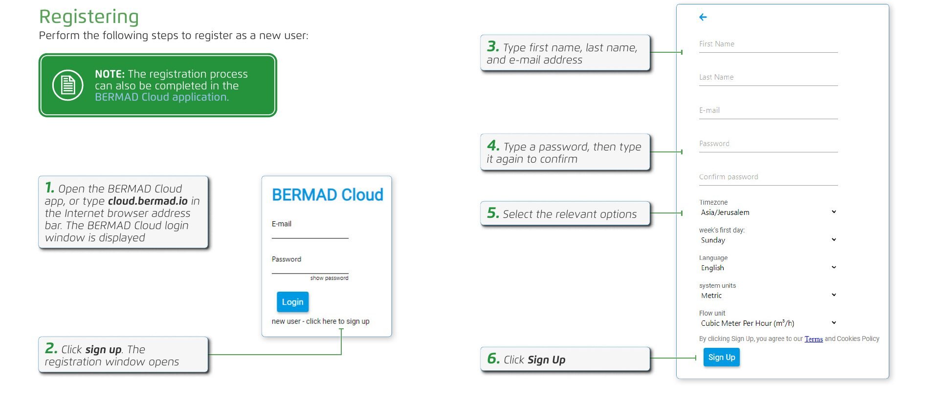
Perform the following steps to register as a new user:
- Open the BERMAD Cloud app, or type cloud.bermad.io in the Internet browser address bar. The BERMAD Cloud login window is displayed.
- Click sign up. The registration window opens.
- Type first name, last name, and e-mail address.
- Type a password, then type it again to confirm.
- Select the relevant options.
- Click Sign Up.
The registration process can also be completed in the BERMAD Cloud application.
Logging In
Esta sección aún no está traducida y se muestra en inglés.
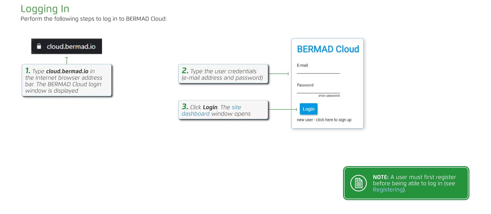
Perform the following steps to log in to BERMAD Cloud:
- Type cloud.bermad.io in the Internet browser address bar. The BERMAD Cloud login window is displayed.
- Type the user credentials (e-mail address and password).
- Click Login. The site dashboard window opens.
A user must first register before being able to log in (see Registering).
Site Dashboard Overview
Esta sección aún no está traducida y se muestra en inglés.
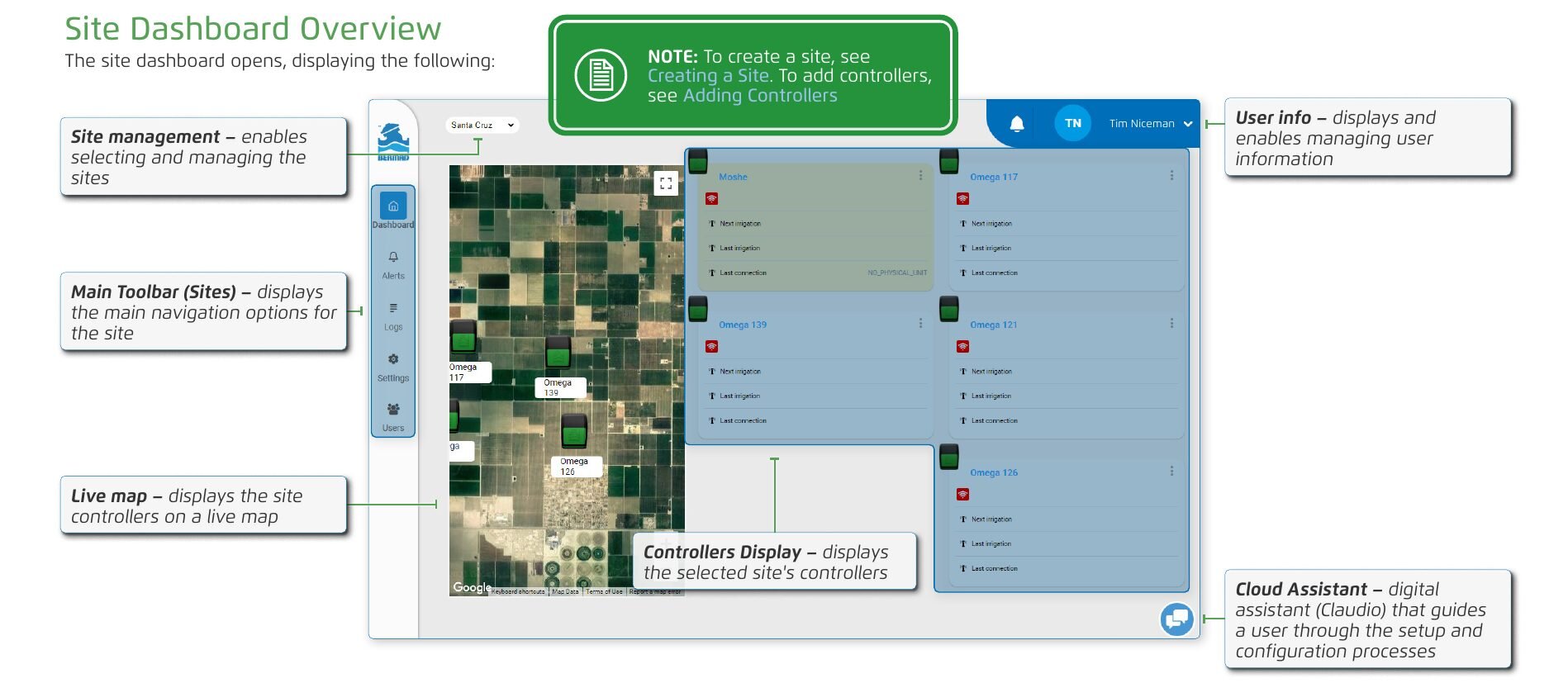
The site dashboard opens, displaying the following:
- Site management – enables selecting and managing the sites.
- User info – displays and enables managing user information.
- Main Toolbar (Sites) – displays the main navigation options for the site.
- Live map – displays the site controllers on a live map.
- Controllers Display – displays the selected site's controllers.
- Cloud Assistant – digital assistant (Claudio) that guides a user through the setup and configuration processes.
To create a site, see Creating a Site. To add controllers, see Adding Controllers.
Managing Sites and Controllers
Esta sección aún no está traducida y se muestra en inglés.
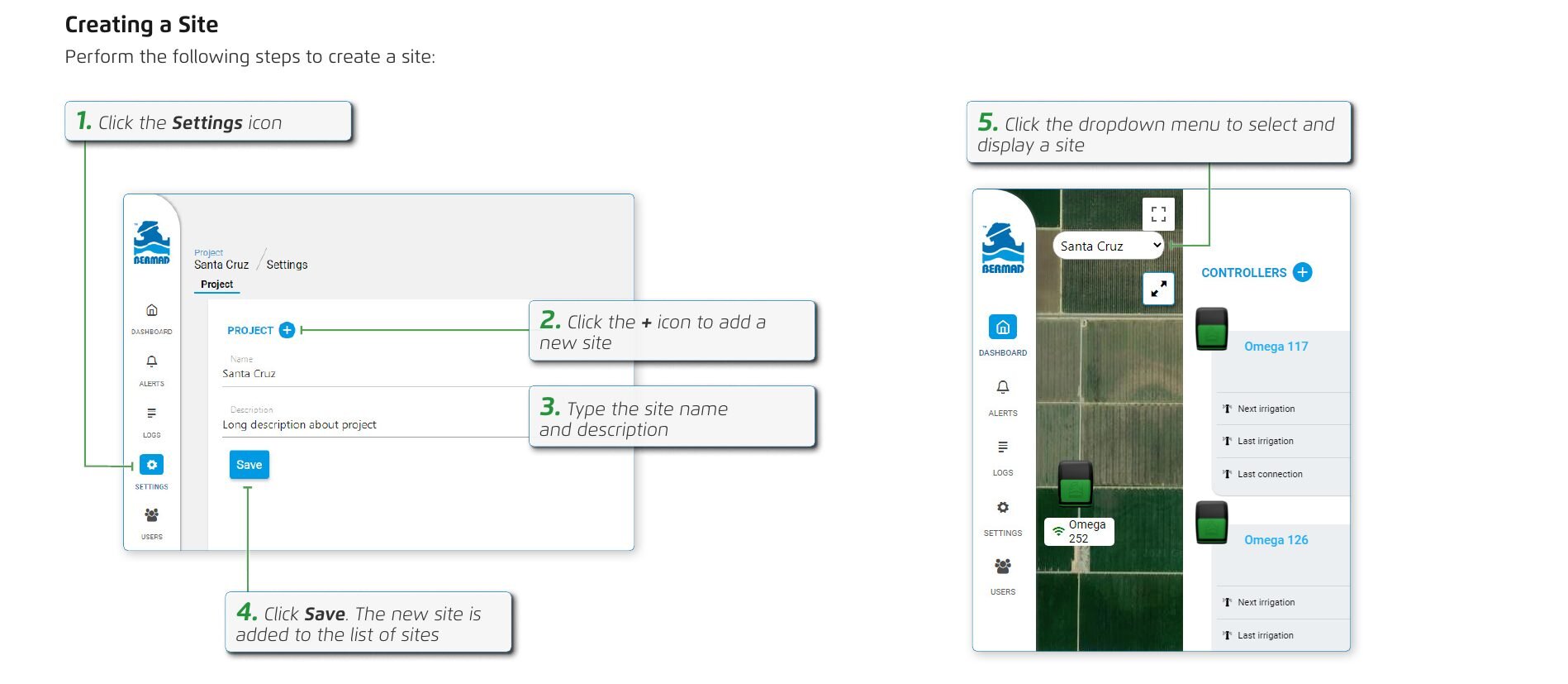
Creating a Site
Perform the following steps to create a site:
- Click the Settings icon.
- Click the + icon to add a new site.
- Type the site name and description.
- Click Save. The new site is added to the list of sites.
- Click the dropdown menu to select and display a site.
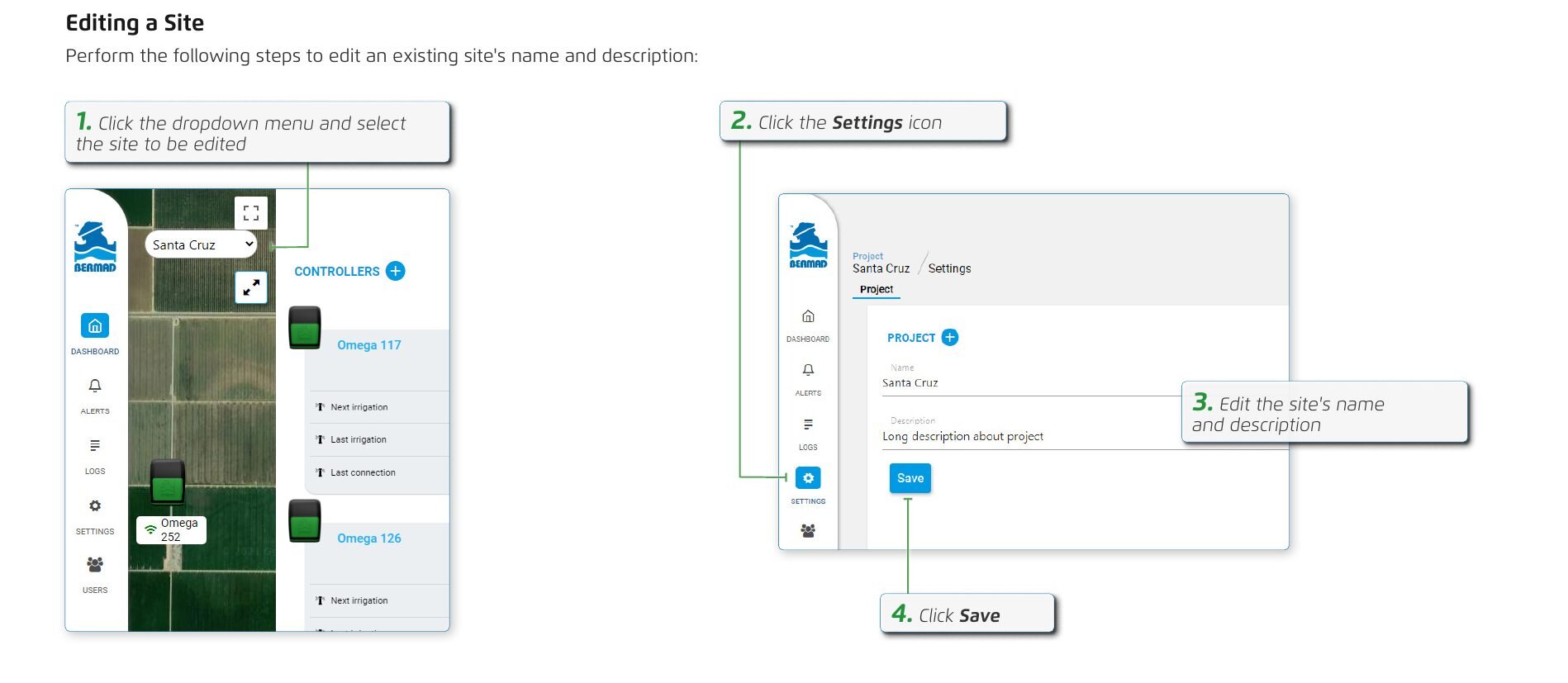
Editing a Site
Perform the following steps to edit an existing site's name and description:
- Click the dropdown menu and select the site to be edited.
- Click the Settings icon.
- Edit the site's name and description.
- Click Save.
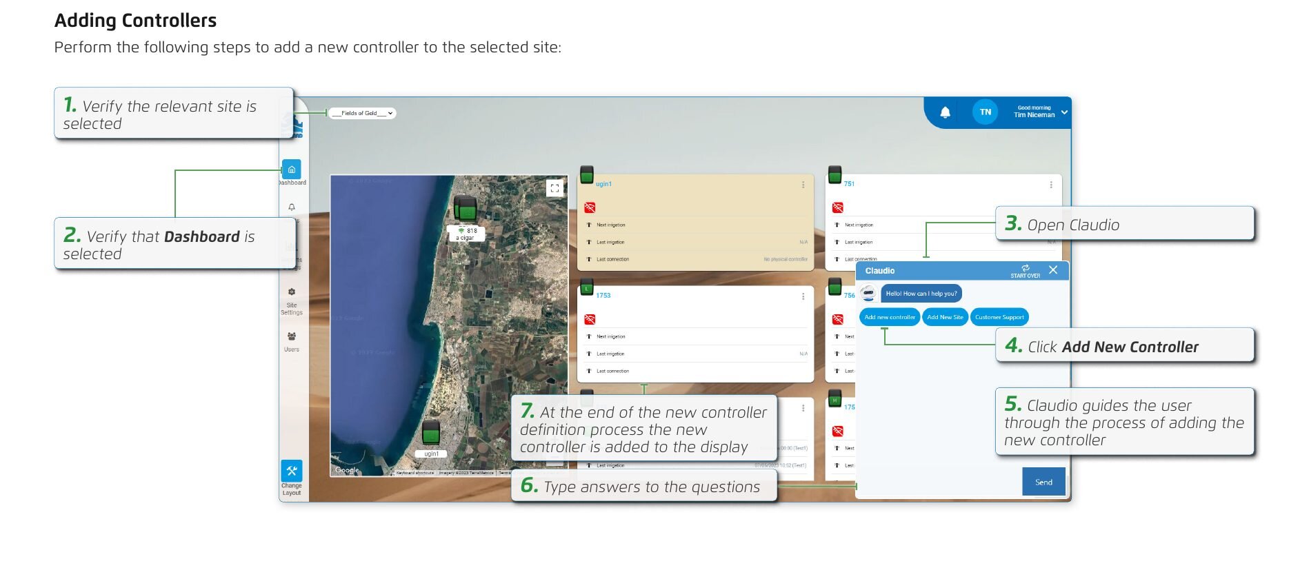
Adding Controllers
Perform the following steps to add a new controller to the selected site:
- Verify the relevant site is selected.
- Verify that Dashboard is selected.
- Open Claudio.
- Click Add New Controller.
- Claudio guides the user through the process of adding the new controller.
- Type answers to the questions.
- At the end of the new controller definition process the new controller is added to the display.
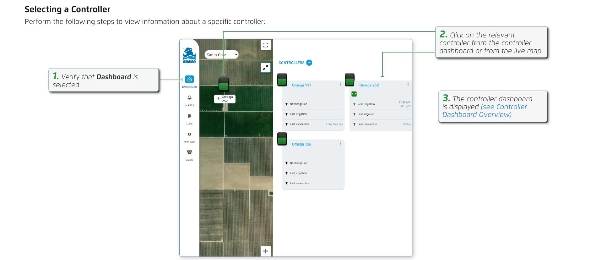
Selecting a Controller
Perform the following steps to view information about a specific controller:
- Verify that Dashboard is selected.
- Click on the relevant controller from the controller dashboard or from the live map.
- The controller dashboard is displayed (see Controller Dashboard Overview).
Controller Dashboard Overview
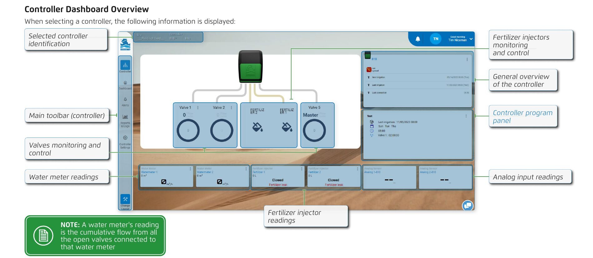
When selecting a controller, the following information is displayed:
- Selected controller identification
- Fertilizer injectors monitoring and control
- General overview of the controller
- Controller program panel
- Main toolbar (controller)
- Valves monitoring and control
- Water meter readings
- Analog input readings
- Fertilizer injector readings
A water meter's reading is the cumulative flow from all the open valves connected to that water meter.
Adding a Device
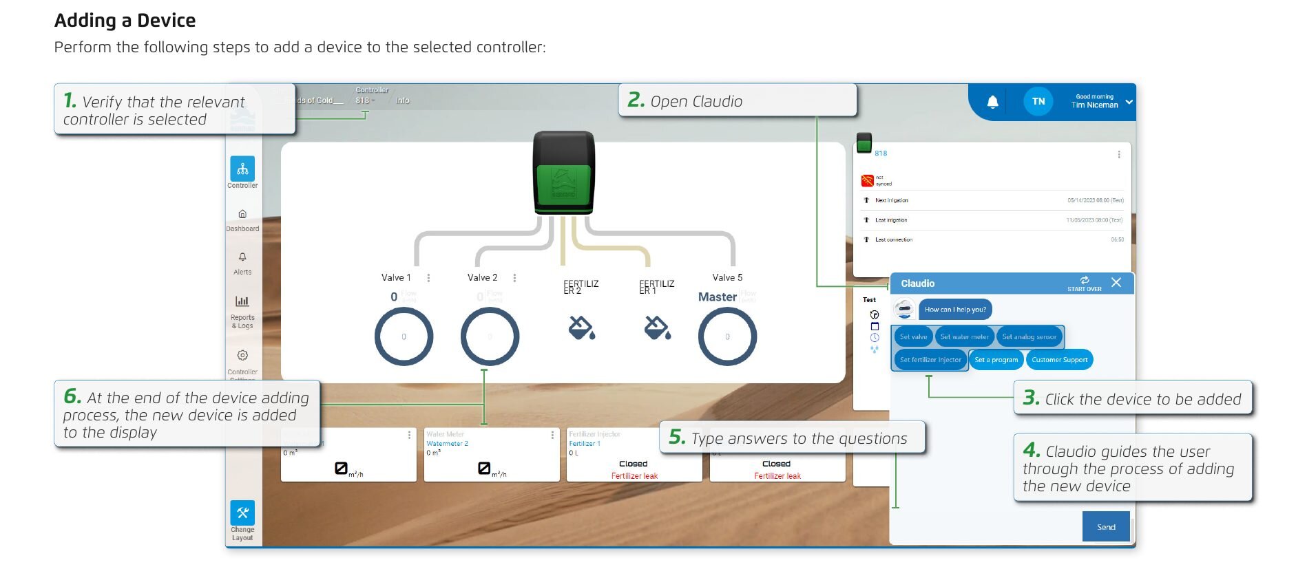
Perform the following steps to add a device to the selected controller:
- Verify that the relevant controller is selected.
- Open Claudio.
- Click the device to be added.
- Claudio guides the user through the process of adding the new device.
- Type answers to the questions.
- At the end of the device adding process, the new device is added to the display.
Basic Device Settings
Esta sección aún no está traducida y se muestra en inglés.
Entering Controller Settings
Perform the following steps to view and modify controller settings:
- Verify that the relevant controller is selected (see Selecting a Controller).
- Click the Controller Settings icon.
- Select the desired setting from the menu.
- The information associated with the selected setting is displayed and can be modified.
General Settings
Perform the following steps to navigate to a controller's general settings:
- From the controller settings, select General.
- The general settings of the controller are displayed.
- Controller name – Enables naming of the controller.
- Serial number – Displays the controller's serial number.
- Last update and sync – Enables synchronizing between the server and controller.
- Site – The site to which the controller belongs. The drop-down list allows the user to move the controller to another site.
- Status – Enables activating and deactivating the controller.
- Controller description – Enables adding text describing the controller.
- Timezone – Defines the time zone in which the controller is located.
- Location – Displays the coordinates of the controller's location. Clicking on the line opens a map which enables moving the controller to a new location. Controller location can also be edited using the smartphone app by clicking Update Controller Location (found under General Settings in the app).
- Master valve – Enables selecting which valve is the master valve.
- Allow programs in parallel – Enables running two or more irrigation programs simultaneously.
- Valves overlapping time – Defines the duration before a valve closes when the next valve opens.
- SIM Number – The controller SIM number.
- Reset to Factory Settings – Click to reset the controller to factory settings.
- Firmware version – Displays the firmware version currently installed on the controller.
If permission to access location is denied when clicking on the location line, in the browser's settings allow cloud.bermad.io to access location and then refresh the page.
Master Valve Settings
The master valve is the valve which controls water flow to all other valves. Perform the following steps to navigate to the master valve's settings:
- From the controller settings, select the valve designated as the master valve.
- The master valve's settings are displayed.
- Valve name – Enables naming of the master valve.
- Output number – The physical output controller to which the master valve is connected.
- Valve description – Enables adding text describing the master valve.
- Opening order – Defines when the master valve opens in relation to the regular valves.
- Closing order – Defines when the master valve closes in relation to the regular valves.
- Opening delay between master & valve – Defines the delay time between opening of the master valve and regular valve. This delay is relevant when either the "master valve before valve" or "valve before master valve" opening order was selected.
- Closing delay – Defines the delay time between closing of the master valve and regular valve. This delay is relevant when either the "master valve before valve" or "valve before master valve" closing order was selected.
The master valve is selected in General Settings.
Valve Settings
Perform the following steps to navigate to the valve settings:
- From the controller settings, select the relevant valve.
- The valve's settings are displayed.
- Valve name – Enables naming of the valve.
- Last update and sync – Enables synchronizing between the server and controller.
- Output number – The physical output controller to which the valve is connected.
- Status – Enables activating and deactivating the valve.
- Valve description – Enables adding text describing the valve.
- Nominal flow – Typical water flow rate passing through the valve.
- Water meter – Enables linking a water meter to the valve.
- Low flow – Low water flow threshold, below which a low flow alert is triggered. The threshold is defined as the decrease in percentage of flow in reference to the nominal flow.
- High flow – High water flow level, above which a high flow alert is triggered. The threshold is defined as the increase in percentage of flow in reference to the nominal flow.
- Flow alert delay – The amount of time a high or low flow trigger is on before an alarm is created.
- Line fill-up time – Amount of time before water fills the pipe and achieves a steady flow.
- Reaction to 'No Pulse' alert – Defines the action taken when there is no response from the water meter while the valve is open.
- Enable long runtime – Enables setting the valve to stay open for longer.
- Delete button – Enables deleting the valve.
Fertilizer Injectors Settings
Perform the following steps to manage the fertilizer injector settings:
- From the controller settings, select the relevant fertilizer injector.
- The fertilizer injector's settings are displayed.
- Fertilizer Injector Name – Enables naming of the fertilizer injector.
- Last update and sync – Enables synchronizing between the server and controller.
- Injector description – Enables adding text describing the fertilizer injector.
- Output number – The output number to which the fertilizer injector valve is connected.
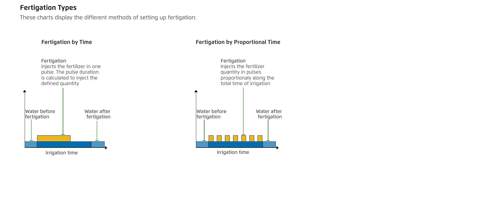
- Fertigation type – Time: Injects the fertilizer in one pulse. The pulse duration is calculated to inject the defined quantity. Proportional Time: Injects the fertilizer quantity in pulses proportionaly along the total time of irrigation (excluding the Water Before and Water After duration). Volume: Injects the fertilizer in one pulse. The fertilizer injector will be activated until the required fertilizer volume has been counted. This option is only relevant if a fertilizer meter is used. Proportional Volume: Injects the fertilizer quantity in pulses proportionaly along the total volume of irrigation (excluding the Water Before and Water After duration). This option is only relevant if a fertilizer meter is used. See Fertigation Overview for more details.
- Status – Enables activating and deactivating the fertilizer injector.
- Reaction to 'No Pulse' alert – Defines the action taken when there is no response from the fertilizer meter while the valve is open.
- Last update and sync – Enables synchronizing between the server and controller.
- Totalizer – Defines the cumulative volume of fertilizer flowing through the system.
- Fertilizer meter pulse size – Defines the volume of fertilizer which has to flow through the fertilizer meter to transmit a pulse.
- Input number – Defines the fertigation meter connected to the valve.
- Enable high pulse rate – Enables high speed pulses when using a fertigation meter with a transistor output.
- Delay of fertilizer meter 'No Pulse' alert – The delay time that is counted from the opening of the injector valve and until the system will check for No Pulse alert.
- Number of pulses to activate leak alert – The delay time that is counted from the closing of the injector valve and until the system will check for Leak alert.
- Delete button – Enables deleting the fertilizer injector.
The fertigation type must match the irrigation method. For example: If irrigation is defined by Duration, the fertigation must be set to Time or Proportional Time.
Water Meter Settings
Perform the following steps to navigate to the water meter settings:
- From the controller settings, select the relevant water meter.
- The water meter's settings are displayed.
- Water meter name – Enables naming of the water meter.
- Last update and sync – Enables synchronizing between the server and controller.
- Water meter description – Enables adding text describing the water meter.
- Input number – The physical input controller to which the water meter is connected.
- Water meter pulse size – Defines the volume of water which has to flow through the water meter to transmit a pulse.
- Enable high pulse rate – Enables high speed pulses when using a water meter with a transistor output.
- Delay of meter 'No Pulse' alert – After a valve is opened, an alert is triggered if the defined amount of time has passed and a pulse has not been transmitted.
- Number of pulses to activate leak alert – After all valves have closed, an alert is triggered if the defined number of pulses were transmitted.
- Timeframe for leak detection – Defines the timeframe according to the number of pulses for activating alert.
- Reaction to 'Leak' alert – Action performed when there is no flow reading while the valve is open.
- Delete button – Enables deleting the water meter.
Switch Indicators Settings
Perform the following steps to navigate to the switch indicators settings:
- From the controller settings, select the relevant switch indicator.
- The switch indicator's settings are displayed.
- Switch name – Enables naming of the switch.
- Last update and sync – Enables synchronizing between the server and controller.
- Switch from open to close notification – Enables adding text describing the switch changes from open to close.
- Reaction to change position from open to close – Action performed when switch changes from open to close.
- Switch from close to open notification – Enables adding text describing the switch changes from close to open.
- Reaction to change position from close to open – Action performed when switch changes from close to open.
- Stability delay – Defines the delay time until the switch changes.
- Input number – The physical input controller to which the switch is connected.
- Delete button – Enables deleting the switch indicator.
Analog Input Settings
Perform the following steps to navigate to the analog input settings:
- From the controller settings, select the relevant analog input.
- The analog input's settings are displayed.
- Analog name – Enables naming of the analog device.
- Last update and sync – Enables synchronizing between the server and controller.
- Sensor type – Enables setting the controller's input according to the sensor's analog type. Options include 0-10 V and 4-20 mA.
- Analog number – The physical input controller to which the analog device is connected.
- Physical measurement unit – The unit of the physical condition being measured (e.g., write "bar" if measuring pressure).
- Measuring range – Defines the signal range as the minimum and maximum values of the physical measurement unit designated by the sensor.
- Disable threshold alerts – Enables eliminating the option for setting low and high threshold.
- Low threshold – Enables choosing an action to be performed when the measurement drops below a defined value.
- High threshold – Enables choosing an action to be performed when the measurement exceeds a defined value.
- Delay – Amount of time (in seconds) between when the low/high value threshold is reached and when the alert is triggered.
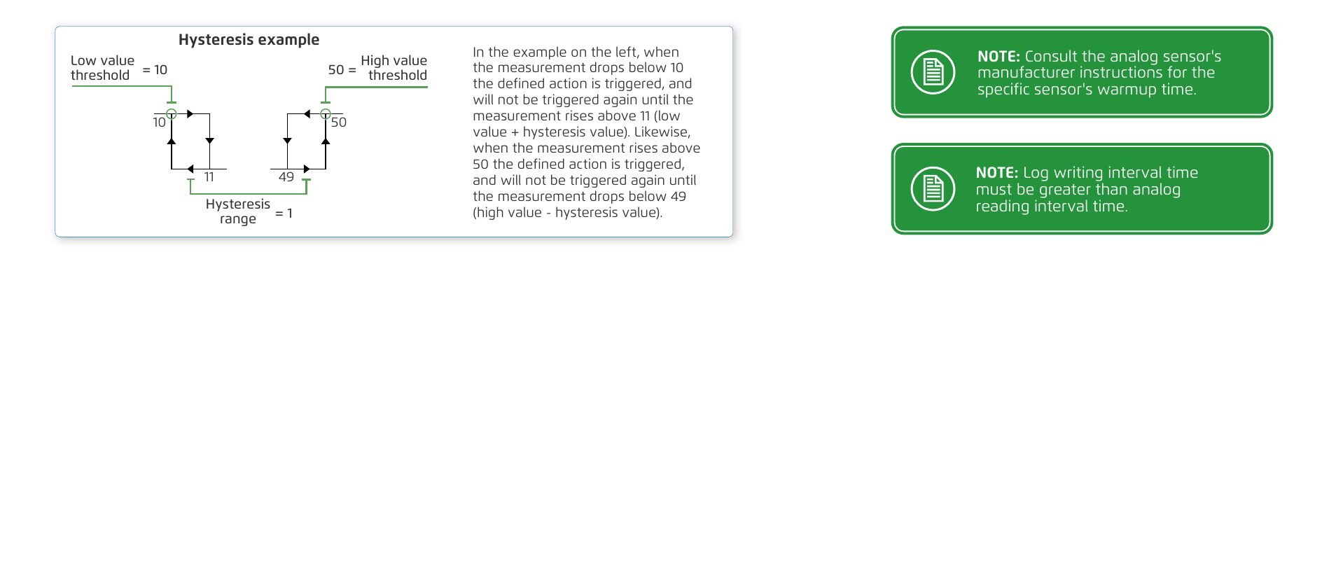
- Hysteresis – Defines a range for both the high and low threshold values. When the threshold values are reached, the action is not triggered again until the value falls out of this range.
- Sampling rate – Defines the number of samples per second at which the analog signal is sampled.
- Warmup time – Defines the time (in seconds) required to energize the sensor before it can perform the measurement.
- Log writing interval – Defines the amount of time between the logging of measurements (see Logs section).
- Delete button – Enables deleting the analog input.
Hysteresis example: With a low value threshold = 10, a high value threshold = 50, and a hysteresis range = 1: when the measurement drops below 10 the defined action is triggered, and will not be triggered again until the measurement rises above 11 (low value + hysteresis value). Likewise, when the measurement rises above 50 the defined action is triggered, and will not be triggered again until the measurement drops below 49 (high value - hysteresis value).
Consult the analog sensor's manufacturer instructions for the specific sensor's warmup time.
Log writing interval time must be greater than analog reading interval time.
Fertigation Overview
Esta sección aún no está traducida y se muestra en inglés.
This section reviews the irrigation when using a fertilizer injector valve.
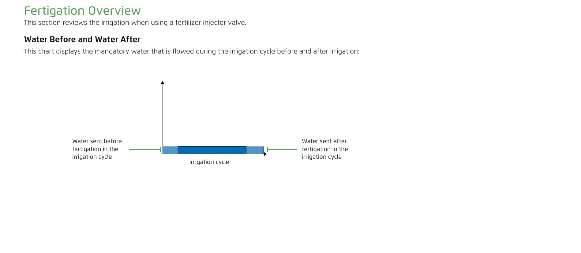
Water Before and Water After
This chart displays the mandatory water that is flowed during the irrigation cycle before and after irrigation:
- Water sent before fertigation in the irrigation cycle.
- Water sent after fertigation in the irrigation cycle.
- Irrigation cycle.
Fertigation Types
These charts display the different methods of setting up fertigation:
- Fertigation by Time – Injects the fertilizer in one pulse. The pulse duration is calculated to inject the defined quantity. Includes water before fertigation and water after fertigation across the irrigation time.
- Fertigation by Proportional Time – Injects the fertilizer quantity in pulses proportionaly along the total time of irrigation. Includes water before fertigation and water after fertigation across the irrigation time.
Managing Programs
Esta sección aún no está traducida y se muestra en inglés.
Program Panel Overview
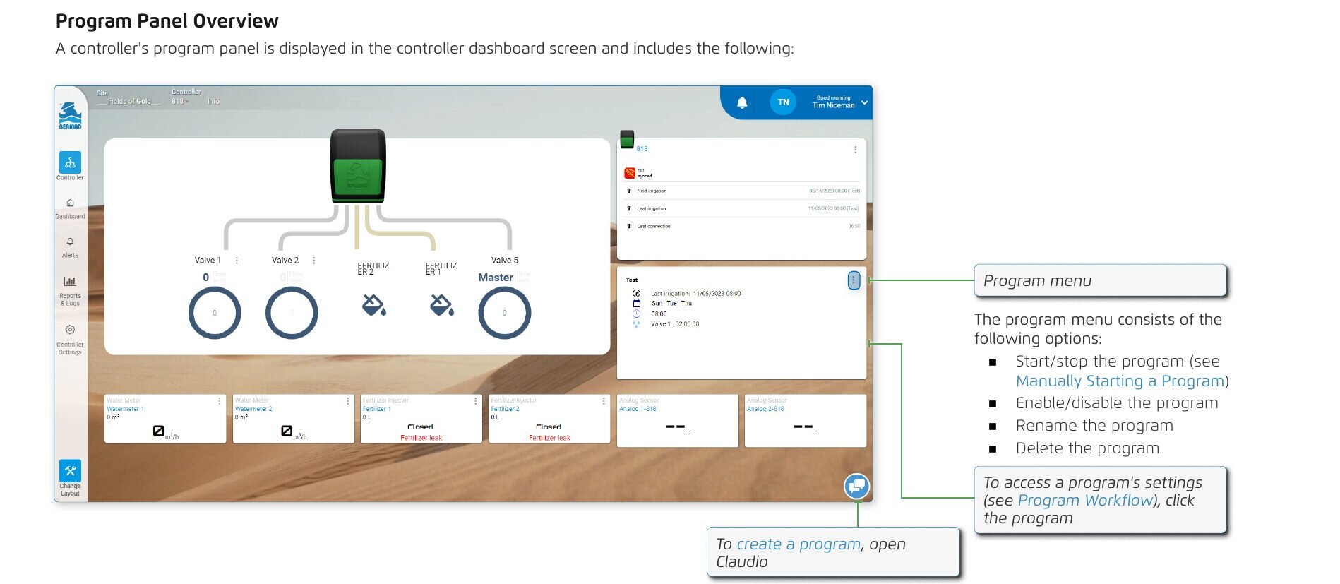
A controller's program panel is displayed in the controller dashboard screen and includes the following. The program menu consists of the following options:
- Start/stop the program (see Manually Starting a Program).
- Enable/disable the program.
- Rename the program.
- Delete the program.
To access a program's settings (see Program Workflow), click the program. To create a program, open Claudio.
Creating a New Program
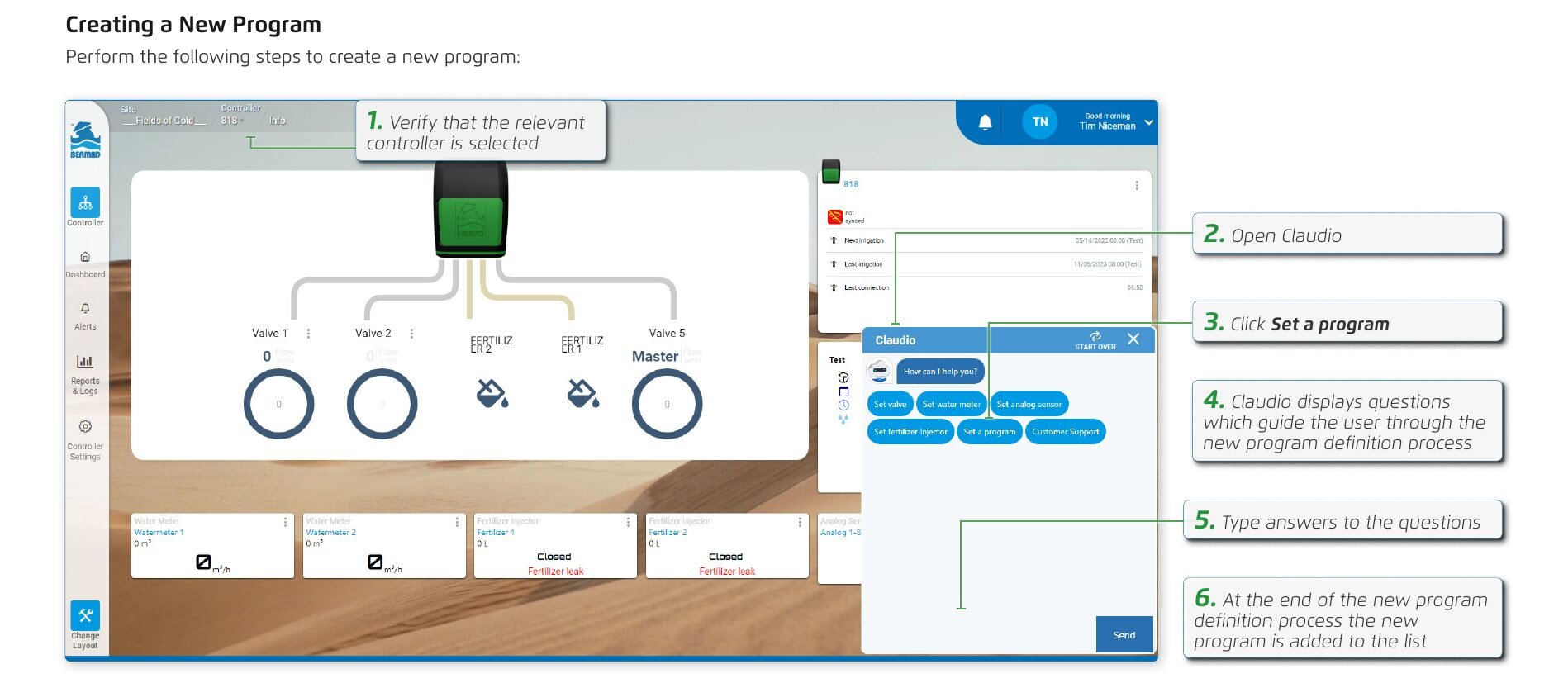
Perform the following steps to create a new program:
- Verify that the relevant controller is selected.
- Open Claudio.
- Click Set a program.
- Claudio displays questions which guide the user through the new program definition process.
- Type answers to the questions.
- At the end of the new program definition process the new program is added to the list.
Program Workflow
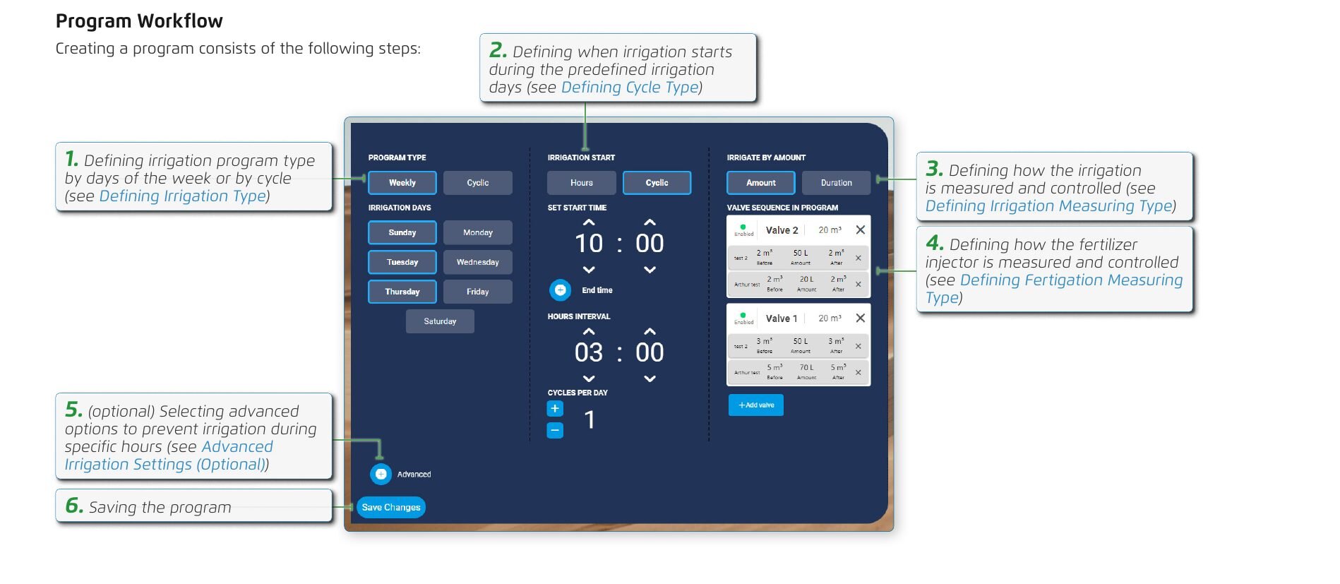
Creating a program consists of the following steps:
- Defining irrigation program type by days of the week or by cycle (see Defining Irrigation Type).
- Defining when irrigation starts during the predefined irrigation days (see Defining Cycle Type).
- Defining how the irrigation is measured and controlled (see Defining Irrigation Measuring Type).
- Defining how the fertilizer injector is measured and controlled (see Defining Fertigation Measuring Type).
- (optional) Selecting advanced options to prevent irrigation during specific hours (see Advanced Irrigation Settings (Optional)).
- Saving the program.
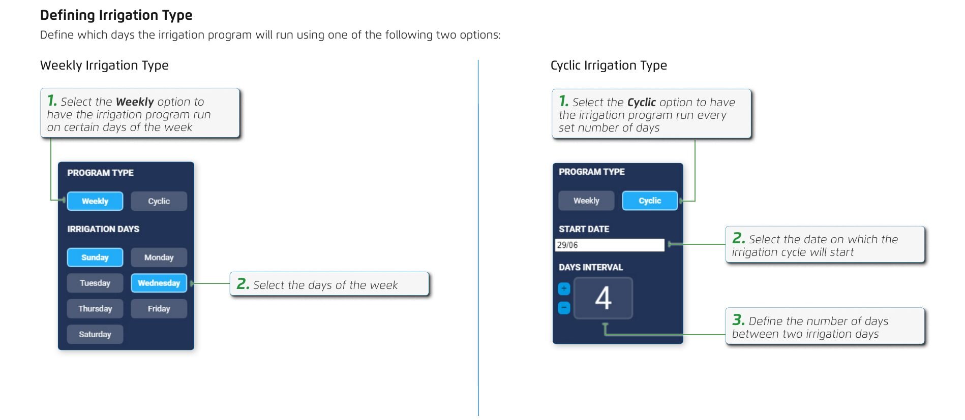
Defining Irrigation Type
Define which days the irrigation program will run using one of the following two options:
Weekly Irrigation Type:
- Select the Weekly option to have the irrigation program run on certain days of the week.
- Select the days of the week.
Cyclic Irrigation Type:
- Select the Cyclic option to have the irrigation program run every set number of days.
- Select the date on which the irrigation cycle will start.
- Define the number of days between two irrigation days.
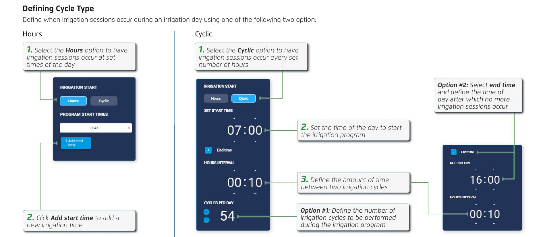
Defining Cycle Type
Define when irrigation sessions occur during an irrigation day using one of the following two options:
Hours:
- Select the Hours option to have irrigation sessions occur at set times of the day.
- Click Add start time to add a new irrigation time.
Cyclic:
- Select the Cyclic option to have irrigation sessions occur every set number of hours.
- Set the time of the day to start the irrigation program.
- Define the amount of time between two irrigation cycles.
- Option #1: Define the number of irrigation cycles to be performed during the irrigation program.
- Option #2: Select end time and define the time of day after which no more irrigation sessions occur.
Defining Irrigation Measuring Type
Define the method used to control the amount of water used during an irrigation session using one of the following two options:
Amount Measuring Type:
- Select the Amount option to have a water meter control the volume of water used per irrigation session.
- Click to add a new valve to the program.
- Select the valve and set the volume of water.
- Click Save.
Duration Measuring Type:
- Select the Duration option to have a timer control the amount of water used per irrigation session.
- Click to add a new valve to the program.
- Select the valve and set the irrigation duration.
- Click Save.
The top valve in the list will start irrigating, followed by the other valves in sequence according to their order in the list.
Defining Fertigation Measuring Type
Define the method used to control the amount of fertilizer injector used during an irrigation session (see Fertilizer Injectors Settings) using one of the following two options:
Amount Measuring Type:
- Select the Amount option to have a water meter control the volume of water used per irrigation session.
- Select the valve and set the volume of water.
- Select the fertigation.
- Set the volume of waterflow before fertigation.
- Set the volume of fertigation.
- Set the volume of waterflow after fertigation.
- Click Save.
- Click Save.
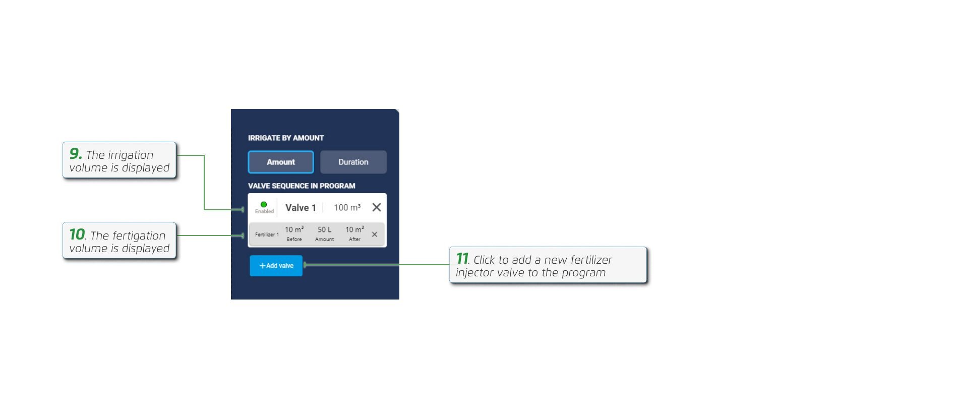
- The irrigation volume is displayed.
- The fertigation volume is displayed.
- Click to add a new fertilizer injector valve to the program.
These options are only relevant if there is a fertilizer injector connected to the controller.
Duration Measuring Type:
- Select the Duration option to have a timer control the amount of water used per irrigation session.
- Click to add a new valve to the program.
- Select the valve and set the irrigation duration.
- Select the fertigation.
- Set the waterflow duration before fertigation.
- Set the fertigation duration.
- Set the waterflow duration after fertigation.
- Click Save.
- Click Save.
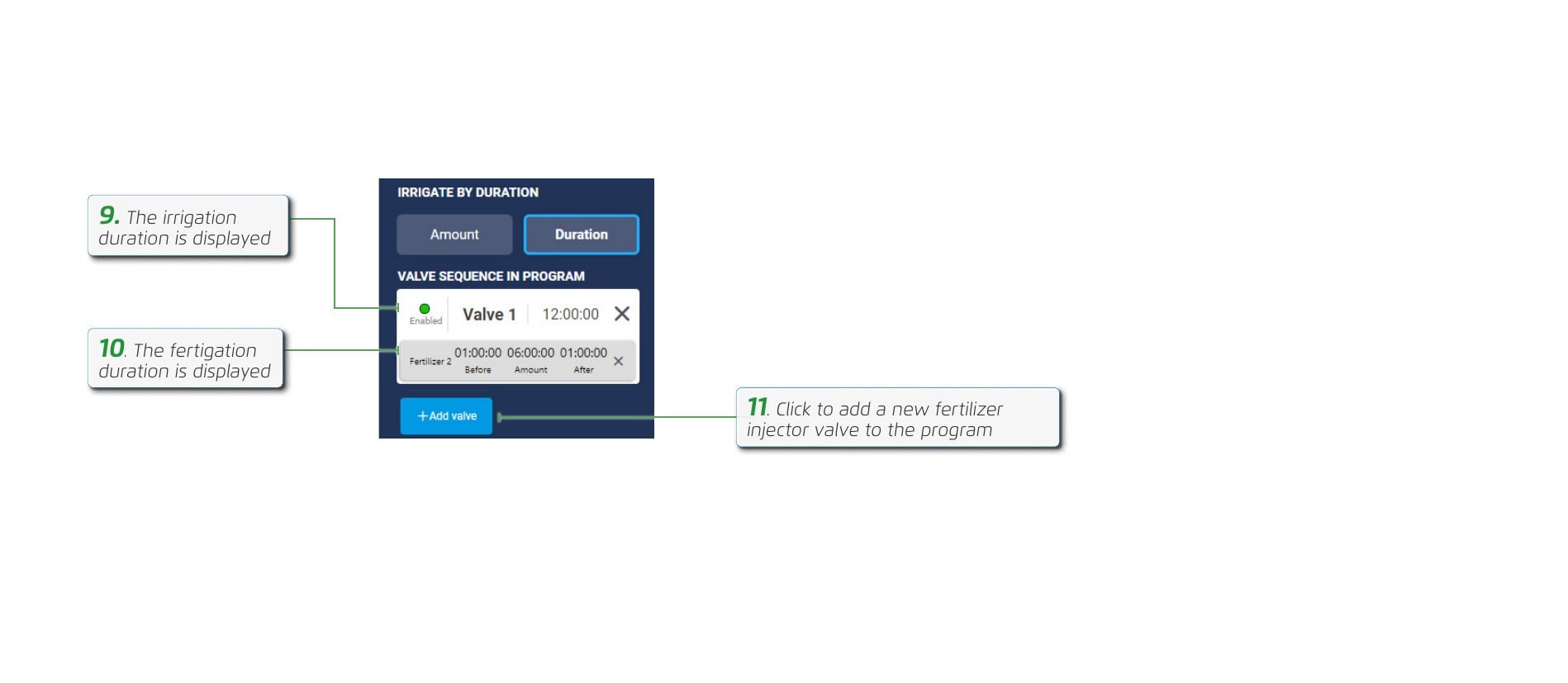
- The irrigation duration is displayed.
- The fertigation duration is displayed.
- Click to add a new fertilizer injector valve to the program.
This option is only relevant if there is a fertilizer meter connected to the controller.
Advanced Irrigation Settings (Optional)
Perform the following steps to limit irrigation to a predefined time period during the irrigation day:
- Click Advanced.
- Set the beginning time of the permitted irrigation time of the day.
- Set the ending time of the permitted irrigation time of the day.
Additional Device Settings
Esta sección aún no está traducida y se muestra en inglés.
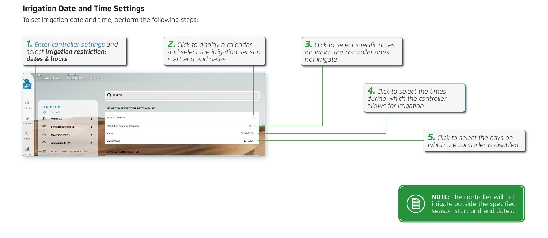
Irrigation Date and Time Settings
To set irrigation date and time, perform the following steps:
- Enter controller settings and select irrigation restriction: dates & hours.
- Click to display a calendar and select the irrigation season start and end dates.
- Click to select specific dates on which the controller does not irrigate.
- Click to select the times during which the controller allows for irrigation.
- Click to select the days on which the controller is disabled.
The controller will not irrigate outside the specified season start and end dates.
Alerts Reaction
To define how the controller responds when there's an alert, perform the following steps:
- Enter controller settings and select general alerts reaction.
- Select the relevant action for each alert.
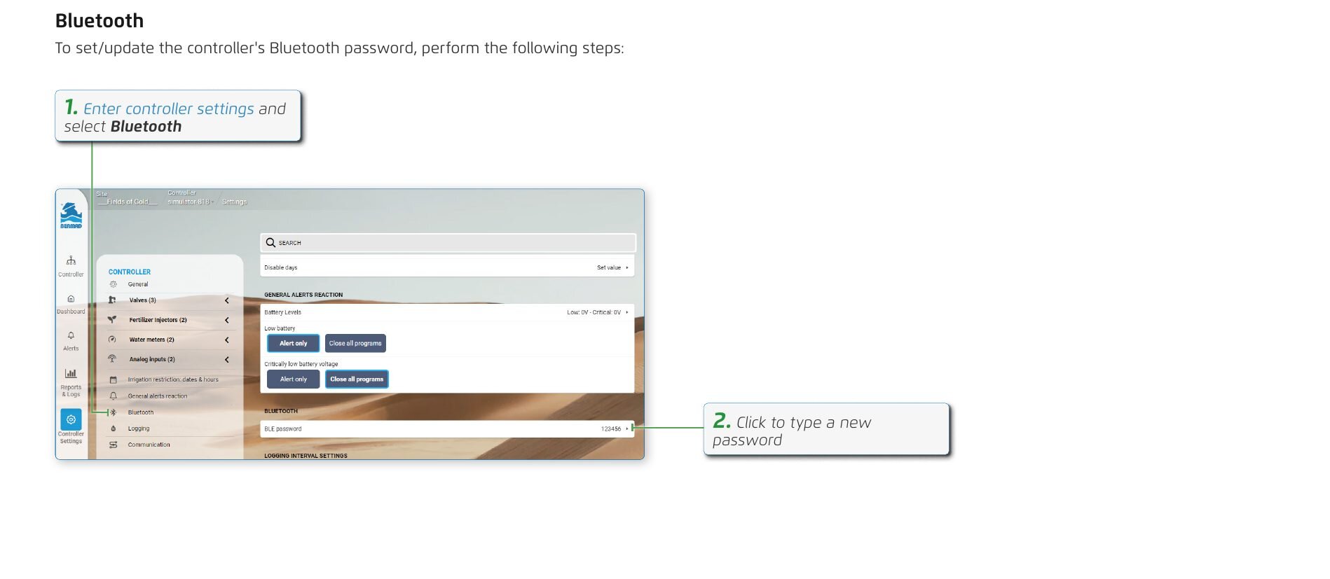
Bluetooth
To set/update the controller's Bluetooth password, perform the following steps:
- Enter controller settings and select Bluetooth.
- Click to type a new password.
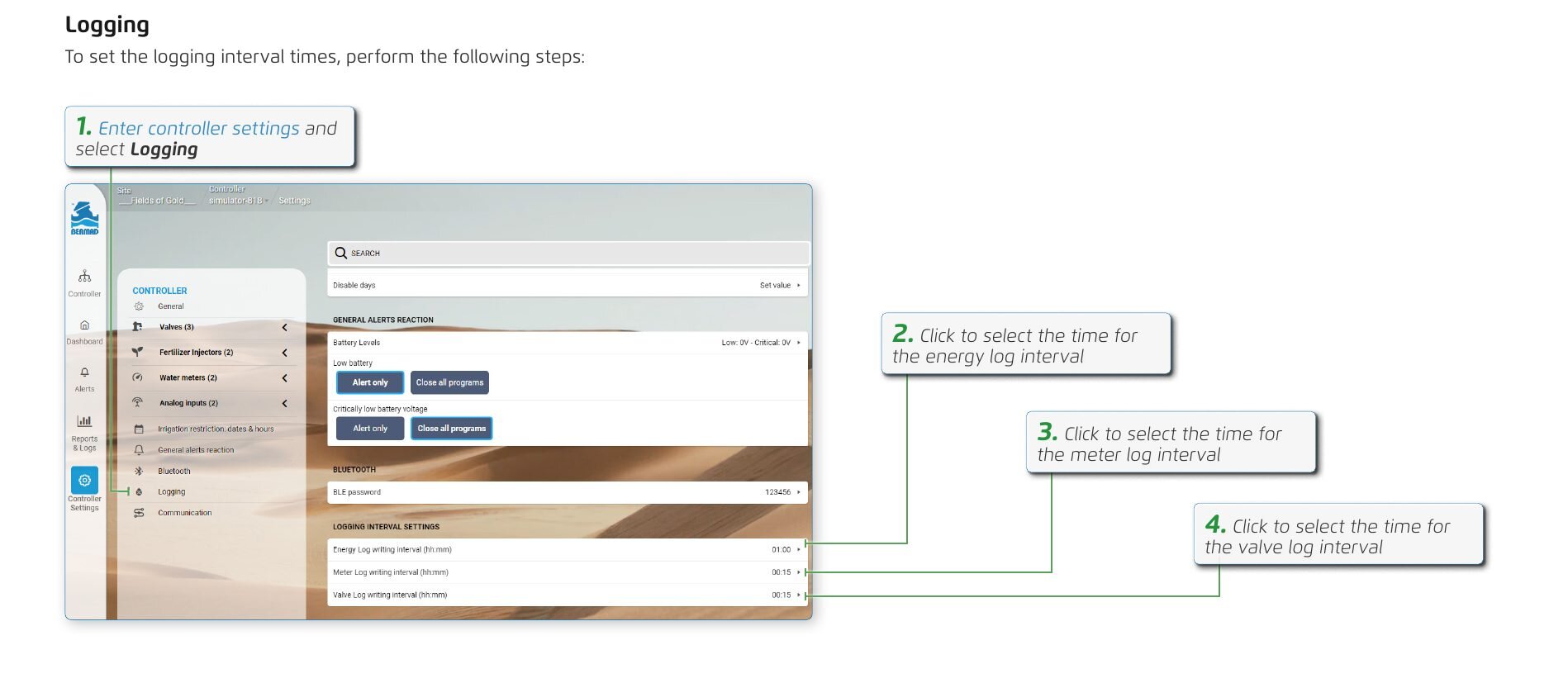
Logging
To set the logging interval times, perform the following steps:
- Enter controller settings and select Logging.
- Click to select the time for the energy log interval.
- Click to select the time for the meter log interval.
- Click to select the time for the valve log interval.
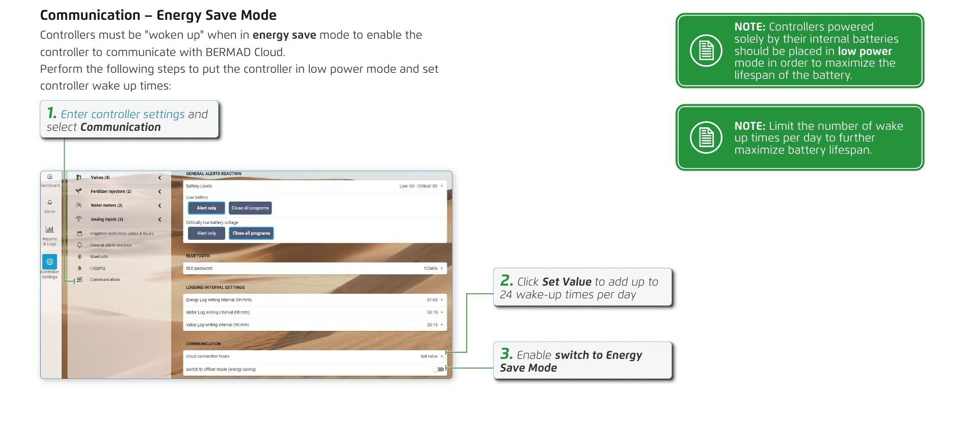
Communication – Energy Save Mode
Controllers must be "woken up" when in energy save mode to enable the controller to communicate with BERMAD Cloud. Perform the following steps to put the controller in low power mode and set controller wake up times:
- Enter controller settings and select Communication.
- Click Set Value to add up to 24 wake-up times per day.
- Enable switch to Energy Save Mode.
Controllers powered solely by their internal batteries should be placed in low power mode in order to maximize the lifespan of the battery.
Limit the number of wake up times per day to further maximize battery lifespan.

Managing Users
Esta sección aún no está traducida y se muestra en inglés.
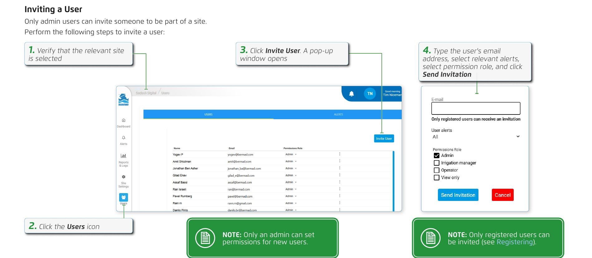
Inviting a User
Only admin users can invite someone to be part of a site. Perform the following steps to invite a user:
- Verify that the relevant site is selected.
- Click the Users icon.
- Click Invite User. A pop-up window opens.
- Type the user's email address, select relevant alerts, select permission role, and click Send Invitation.
Only an admin can set permissions for new users.
Only registered users can be invited (see Registering).
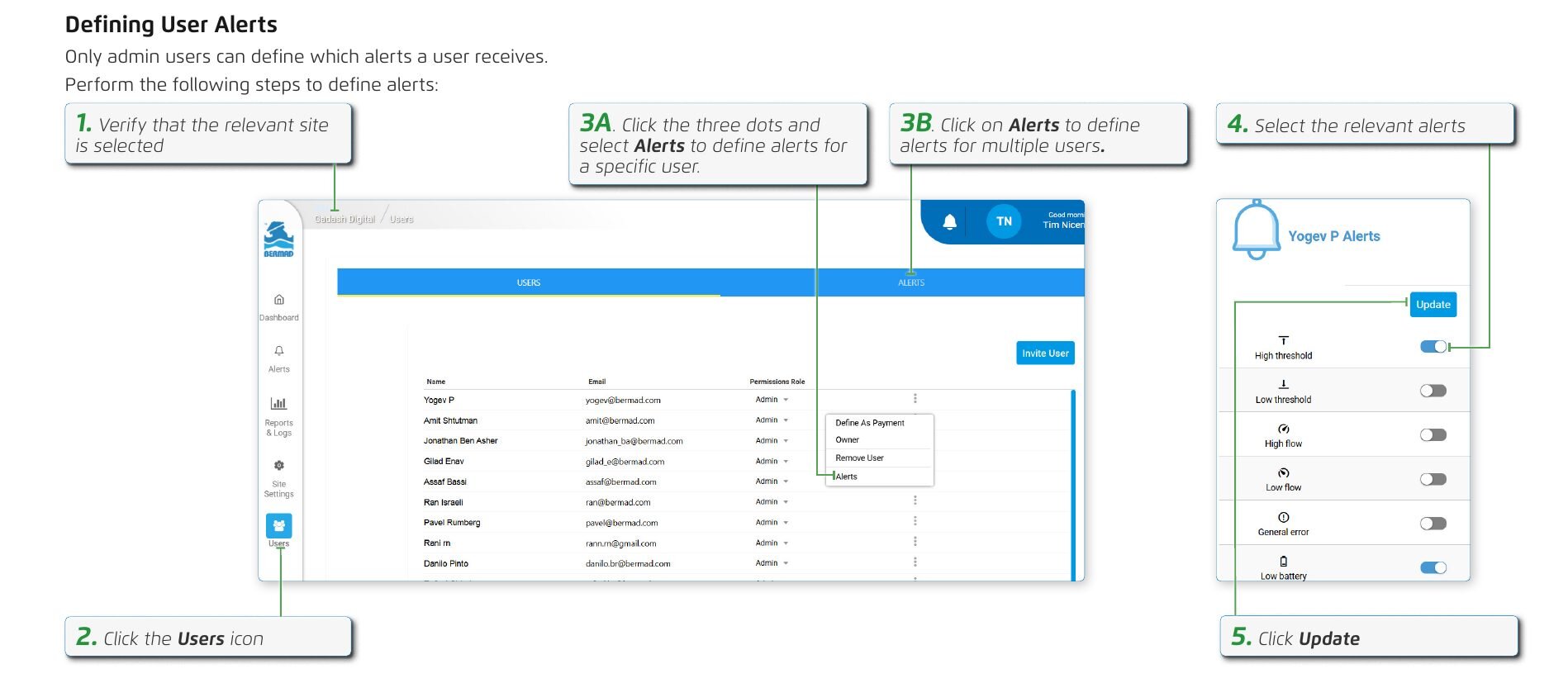
Defining User Alerts
Only admin users can define which alerts a user receives. Perform the following steps to define alerts:
- Verify that the relevant site is selected.
- Click the Users icon.
- 3A. Click the three dots and select Alerts to define alerts for a specific user.
- 3B. Click on Alerts to define alerts for multiple users.
- Select the relevant alerts.
- Click Update.
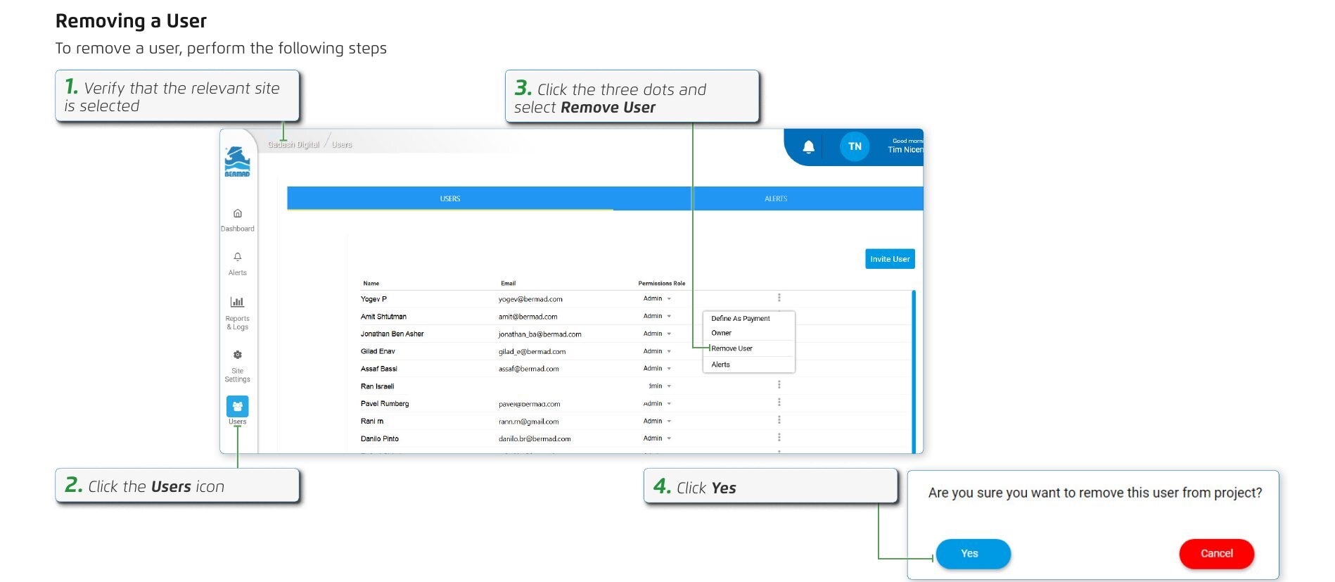
Removing a User
To remove a user, perform the following steps:
- Verify that the relevant site is selected.
- Click the Users icon.
- Click the three dots and select Remove User.
- Click Yes.
5. Monitoring Controllers
Manually Operating Valves
Esta sección aún no está traducida y se muestra en inglés.
To manually open valves, perform the following steps:
- Verify that the relevant controller is selected
- Open the valve menu and select Start. A pop-up window opens
- Select whether amount of water to be used is determined by duration or volume
- Set the desired volume
- Click Open Valve
- The valve remains open until the set amount of water is used
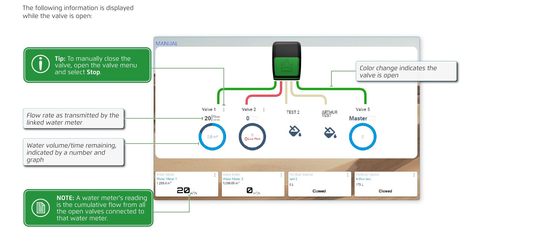
The following information is displayed while the valve is open:
- Color change indicates the valve is open
- Flow rate as transmitted by the linked water meter
- Water volume/time remaining, indicated by a number and graph
To manually close the valve, open the valve menu and select Stop.
A water meter's reading is the cumulative flow from all the open valves connected to that water meter.
Manually Starting a Program
Esta sección aún no está traducida y se muestra en inglés.
To manually start a program, perform the following steps:
- Open the program menu
- Click Start Program
Alerts
Esta sección aún no está traducida y se muestra en inglés.
To view alerts, perform the following steps:
- Verify that the relevant site is selected
- Click the Alerts icon
- Click Filter to enable filtering the alerts by date and by unit
- Clicking the refresh icon will sync the alerts data.
- Alerts can be exported to a PDF or CSV file.
Logs
Esta sección aún no está traducida y se muestra en inglés.
To view a log of irrigation sessions, perform the following steps:
- Verify that the relevant controller is selected
- Click the Reports & Logs icon
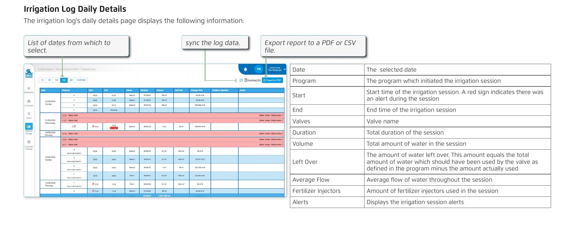
- Click Details to open a new window with a detailed record of daily sessions (see Irrigation Log Daily Details)
The graphs display information on irrigation, water meter accumulation, user actions, valve accumulation, energy, system and fertigation meter accumulation
Irrigation Log Daily Details
The irrigation log's daily details page displays the following information:
- List of dates from which to select.
- sync the log data.
- Export report to a PDF or CSV file.
| Field | Description |
|---|---|
| Date | The selected date |
| Program | The program which initiated the irrigation session |
| Start | Start time of the irrigation session. A red sign indicates there was an alert during the session |
| End | End time of the irrigation session |
| Valves | Valve name |
| Duration | Total duration of the session |
| Volume | Total amount of water in the session |
| Left Over | The amount of water left over. This amount equals the total amount of water which should have been used by the valve as defined in the program minus the amount actually used |
| Average Flow | Average flow of water throughout the session |
| Fertilizer Injectors | Amount of fertilizer injectors used in the session |
| Alerts | Displays the irrigation session alerts |
6. Specifications
Technical Specifications
Esta sección aún no está traducida y se muestra en inglés.
6. Specifications
| Specification | Value |
|---|---|
| Power source | Battery: four LR14 (C-size) alkaline batteries (up to 5 years operation in offline mode). External: 9-16 VDC power input (online mode operation - solar panel, grid power, etc.) |
| Data logging | more than 150,000 records |
| Firmware upgrades | periodic "firmware over the air" (FOTA) upgrades |
| Environment | IP65 rated with UV protection |
| Standards compliance | FCC and CE |
| Operating temperature | -35 °C-31 °F to 75 °C167 °F |
| Connectors | push type without need for special tools |
Dimensions
Adaptor types: Wall mounted, With globe valve adaptor, With oblique valve adaptor*
| Measure | Value |
|---|---|
| No. of units | 1 |
| Length | 21 cm8.3 in |
| Width | 25 cm9.8 in |
| Height | 8 cm3.1 in |
| Gross weight | 1.325 kg2.921 lb |
7. Warranty
Standard International Limited Warranty
Esta sección aún no está traducida y se muestra en inglés.
BERMAD Standard International Limited Warranty
Product Details: OMEGA irrigation controller (the "Product")
BERMAD CS LTD. (“BERMAD”) warrants that, for a period of 24 months from the retail purchase date of the original (first) purchaser (the "Warranty Period"), each component of the Product shall be free from defects in material or workmanship and the Product shall meet in all material respects its specification as detailed in BERMAD documentations.
General Conditions
This warranty shall be valid only if the Product is installed, handled and maintained in accordance with BERMAD's written manual provided together with the Products or publish on BERMAD website.
This Warranty does not cover defects or damages resulting from accident, inappropriate physical or operational environment, failure of electrical power, 'acts of nature' (which includes but is not limited to, hail, lightning storm, blizzard, flood and fire effects), improper installation, maintenance, service, repair, transportation, storage, modification, operation, use, damage by animals, negligence or fault by any party other than BERMAD.
This Warranty shall run solely to and in favor of the customer that purchased the defective Product directly from BERMAD (or any of its authorized dealers), and it does not extend to any other purchaser or user of the Product.
Claims, Notifications and Compensation
Every warranty claim must be notified in writing to BERMAD (or to the relevant authorized dealer from which the Product was purchased) as soon as reasonably possible after the discovery of the defective Product, enclosing the original sales receipt and this Warranty.
The claimant must allow BERMAD to inspect the Product involved and the installation site itself while the Product is still in its original position and has not been removed or altered in any way and/or return the Product to BERMAD for testing. BERMAD reserves the right to investigate independently the cause of any failure.
If a claim under this Warranty is properly notified within the Warranty Period and found to be justified by BERMAD, then BERMAD, at its sole option, shall: (i) replace such Product; or (ii) repair such Product.
In any way, BERMAD’s liability shall not exceed the amounts actually paid by the customer to BERMAD (or to any of its authorized dealers) for the defective Products.
Limitations
This Warranty is the sole warranty in respect to the Products.
Under no circumstances shall BERMAD be liable for any indirect, special or consequential damages, including, without limitation, for any loss of profit, loss in connection with business interruption, loss of use, loss of revenues or damage to business or reputation.
This warranty does not cover any costs and expenses of removal and installation of the Product or shipping cost or taxes or any other direct or indirect loss(es) which may result from the Product failure and BERMAD shall not be liable for such costs and expenses.
OTHER THAN HAS BEEN SPECIFICALLY STATED IN THIS WARRANTY, ALL OTHER WARRANTIES, WHETHER EXPRESS OR IMPLIED, INCLUDING ALL IMPLIED WARRANTIES OF FITNESS FOR A PARTICULAR PURPOSE ARE EXCLUDED SO FAR AS THE LAW PERMITS.